semi合集-English.pdf - 第712页
SEMI E99-1104 E © SEMI 2000, 2004 2 write capability, in some cases the user may designate a portion of t he data to be used as a carri er ID. 5.2.4 carrier ID reader — a unit (subsystem) that detects and dec odes data f…

SEMI E99-1104
E
© SEMI 2000, 2004 1
SEMI E99-1104
E
THE CARRIER ID READER/WRITER FUNCTIONAL STANDARD:
SPECIFICATION OF CONCEPTS, BEHAVIOR, AND SERVICES
This specification was technically approved by the Global Information and Control Committee and is the
direct responsibility of the Japanese Information and Control Committee. Current edition approved by the
North American Regional Standards Committee on January 10, 2003. Initially available at www.semi.org
January 2003; to be published March 2003. Originally published February 2000; previously published March
2003.
E
This standard was editorially modified in September 2004 to correct an error. Change was made to Section
R4.1.1.3.
NOTICE: The designation of SEMI E99 was updated during the 1104 publishing cycle to reflect changes to SEMI
E99.1.
1 Purpose
1.1 The purpose of the Carrier ID Reader/Writer
Functional Standard effort is to provide a common
specification for concepts, behavior, and services
(functions) provided by a Carrier ID Reader and a
Carrier ID Reader/Writer to an upstream controller. A
standard interface will increase interchangeability of
Carrier ID Reader/Writers so that users and equipment
suppliers have a wider range of choices.
2 Scope
2.1 The Carrier ID Reader/Writer Interface Standard
addresses the functional requirements for a generic
Carrier ID Reader/Writer interface with an upstream
controller.
2.2 The specification includes required behavior and
required communications for both a Carrier ID Reader
and a Carrier ID Reader/Writer.
2.3 This specification does not require, define, or
prohibit asynchronous messages sent by the Carrier ID
Reader or Reader/Writer.
NOTICE: This standard does not purport to address
safety issues, if any, associated with its use. It is the
responsibility of the users of this standard to establish
appropriate safety and health practices and determine
the applicability of regulatory or other limitations prior
to use.
3 Limitations
3.1 This standard does not define the specific protocol
to be used for the Carrier ID Reader/Writer.
Supplements to this standard are required to describe
how the functions of the Carrier ID Reader/Writer are
implemented for specific protocols.
4 Referenced Standards
4.1 SEMI Standards
SEMI E1.9 Mechanical Specification for Cassettes
Used to Transport and Store 300 mm Wafers
SEMI E15 Specification for Tool Load Port
SEMI E30 Generic Model for Communications and
Control of Manufacturing Equipment (GEM)
SEMI E39 Object Services Standard: Concepts,
Behavior, and Services
SEMI E47.1 Provisional Mechanical Specification
for Boxes and Pods Used to Transport and Store 300
mm Wafers
SEMI E62 Provisional Specification for 300 mm
Front-Opening Interface Mechanical Standard (FIMS)
SEMI E87 — Specification for Carrier Management
(CMS)
NOTICE: As listed or revised, all documents cited
shall be the latest publications of adopted standards.
5 Terminology
5.1 Abbreviations and Acronyms
5.1.1 CIDRW — represents both the Carrier ID Reader
and the Carrier ID Reader/Writer
5.1.2
FOUP — Front Opening Unified Pod
5.2 Definitions
5.2.1 attribute — information about or associated with
some entity or object.
5.2.2 carrier — 1. a container, such as a FOUP or open
cassette, with one or more positions for holding
substrates (SEMI E87). 2. any cassette, box, pod, or
boat that contains wafers.
5.2.3 carrier ID — an identifier for a carrier. A value
that uniquely identifies a given carrier in a factory. The
identifier may be represented physically with any one
of various technologies. For electronic tags with read/

SEMI E99-1104
E
© SEMI 2000, 2004 2
write capability, in some cases the user may designate a
portion of the data to be used as a carrier ID.
5.2.4 carrier ID reader — a unit (subsystem) that
detects and decodes data from the ID tag.
5.2.5 carrier ID reader/writer — a unit (subsystem)
with the functionality of both a carrier ID reader and a
carrier ID writer.
5.2.6 carrier ID tag (tag, ID tag) — a physical device
for storing Carrier ID and other information. There are
two basic types of tags, read-only tags and read/write
tags.
5.2.7 carrier ID writer — a unit which encodes data
for and writes it to the carrier ID tag.
5.2.8 cassette — an open structure that holds one or
more substrates.
5.2.9 controller — a system that provides control
(performs required operations when certain conditions
occur or when interpreting and acting upon
instructions) and communicates with a higher level
manager. Controllers exist at all levels within a factory.
Examples of controllers include the Multiple ID
Reader/Writer Controller, the Equipment Controller,
and the Load Port Controller.
5.2.10 front-opening unified pod (FOUP) — a box
(that complies with SEMI E47.1) with a non-removable
cassette (so that its interior complies with SEMI E1.9)
and with a front-opening interface (that mates with a
FIMS port that complies with SEMI E62).
5.2.11 fundamental requirements — the requirements
for information and behavior that must be satisfied for
compliance to a standard. Fundamental requirements
apply to specific areas of application, objects, or
services.
NOTE 1: All portions of the carrier ID reader/writer
specification are considered to be fundamental requirements
unless explicitly described as optional. See also optional
requirement.
5.2.12 load port — the interface location on a tool
where wafer carriers are delivered. It is possible that
wafers are not removed from, or inserted into, the
carrier at this location.
5.2.13 message interleaving — the practice of sending
a new message request before receiving the reply to an
earlier request.
5.2.14 multiple ID reader/writer controller — a unit
controlling the Reader/Writer function of one or
multiple ID Reader/Writer Heads, communicates the
command/data with the equipment controller or the
equivalent controller such as Load port Controller in the
equipment configuration.
5.2.15 optional capability — a specification that is not
required for an implementation to be compliant to a
standard. The supplier developing the CIDWR has the
option to provide these additional capabilities or not
depending on supplier’s product configuration. See also
fundamental requirement.
5.2.16 reader/writer head — a structured portion
which functions to detect the ID code and/or to write
the ID code. The ID reader/writer unifying a head
function inside its body can be placed as a head. The ID
reader/writer not unifying a head function will be
located separately from the head.
5.2.17 tag fault — any condition that causes errors
when reading or writing to the tag, including power
faults and tag damage.
5.2.18 upstream controller — a controller that directs
the Carrier ID Reader/Writer through the communi-
cation interface.
5.3 Data Types
5.3.1 enumerated — may take on one of a limited set
of possible values. These values may be given logical
names, but they may be represented by any single-item
data type.
5.3.2 form — type of data: positive integer, unsigned
integer, integer, floating point (float), enumerated,
boolean, text, formatted text, structure, list, ordered list.
5.3.3 integer — may take on the value of any negative
or unsigned integer. Messaging protocol may impose a
limit on the range of possible values.
5.3.4 structure — a specific set of items, of possibly
mixed data types, in a specified arrangement.
5.3.5 text — a character string. Messaging protocol may
impose restrictions, such as length or ASCII
representation.
5.3.6 unsigned integer — may take on the value of any
positive integer or zero. Messaging protocol may
impose a limit on the range of possible values.
6 Conventions
6.1 State Model Methodology
6.1.1 This document uses the Harel state chart
convention for describing dynamic operation of defined
objects. The outline of this convention is described in
an attachment of SEMI E30. The official definition of
this convention is described in “State Charts: A Visual
Formalism for Complex Systems” written by D. Harel
in Science of Computer Programming 8, 1987
1
.
1 Elsevier Science, P.O. Box 945, New York, NY 10159-0945,
http://www.elsevier.nl/homepage/browse.htt
SEMI E99-1104
E
© SEMI 2000, 2004 3
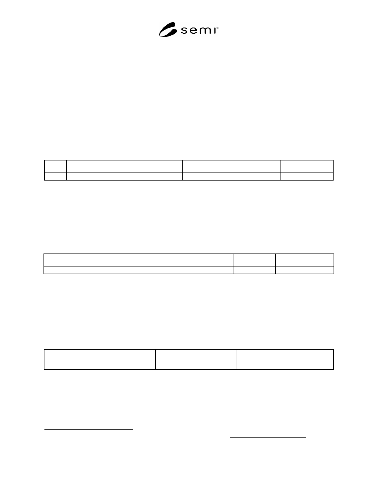
6.1.2 Transition tables are provided in conjunction with the state diagrams to explicitly describe the nature of each
state transition. A transition table contains columns for Transition number, Previous State, Trigger, New State,
Actions, and Comments. The “trigger” (column 3) for the transition occurs while in the “previous” state. The
“actions” (column 5) includes a combination of:
Actions taken upon exit of the previous state.
Actions taken upon entry of the new state.
Actions taken which are most closely associated with the transition.
6.1.2.1 No differentiation is made between these cases.
6.2 Object Notation
6.2.1 The object models in Related Information 2 use the Object Modeling Technique (OMT) developed by
Rumbaugh, James, et al, in Object-Oriented Modeling and Design.
2
An overview of this notation is provided in
SEMI E39, Object Services Standard: Concepts, Behavior, and Services.
Num Previous State Trigger New State Actions Comments
6.3 Service Message Representation
6.3.1 Services are functions or methods that may be provided by either the equipment or the host. A service
message may be either a request message, which always requires a response, or a notification message, that does not
require a response.
6.3.2 Service Definition
6.3.2.1 A service definition table defines the specific set of messages for a given service resource, as shown in the
following table:
Message Service Name Type Description
Type can be either “N” = Notification or “R” = Request & Response.
6.3.2.2 Notification type messages are initiated by the service provider (e.g., the equipment) and the provider does
not expect to get a response from the service user. Request messages are initiated by a service user (e.g., the host).
Request messages ask for data or an activity from the provider. Request messages expect a specific response
message (no presumption on the message content).
6.3.3 Service Parameter Dictionary
6.3.3.1 A service parameter dictionary table defines the description, format and its possible value for parameters
used by services, as shown in the following table:
Parameter Name Description Format: Possible Value
6.3.3.2 A row is provided in the table for each parameter of a service.
2 James Rumbaugh, Michael Blaha, William Premerlani, Frederick Eddy, William Lorensen, Object-Oriented Modeling and Design
, Englewood
Cliffs, New Jersey: Prentice-Hall, 1991.