semi合集-English.pdf - 第514页
SEMI E74-0301 © SEMI 1998 , 2001 3 D: nomina l bore of the outl et flange Top view 1.5D 1.5D X axis the area for the purge gas inlet & the cooling water connectors Purge gas inlet bolt holes the area for the electric…
SEMI E74-0301 © SEMI 1998, 2001 2
ISO 1609 — Vacuum Technology - Flange dimensions
ISO 2861-1 — Vacuum technology - Quick-release
couplings - Dimensions - Part 1: Clamped type
NOTE 1: As listed or revised, all documents cited shall be the
latest publications of adopted standards.
5 Terminology
5.1 pump alarm A cautionary signal that the pump
has stopped or is to be stopped.
5.2 pump warning A state of an abnormal or
extraordinary event during pump operation which
means there is a probability the pump will stop.
5.3 turbomolecular pump (TMP) Equipment used
to create a high vacuum. Rapidly rotating blades force
molecules to the bottom for removal by a mechanical
pump.
5.4 Vacuum Pump A pumping apparatus which
exhausts gas or air from an enclosed space to achieve a
desired degree of vacuum.
6 Requirements
6.1 Mechanical Interfaces
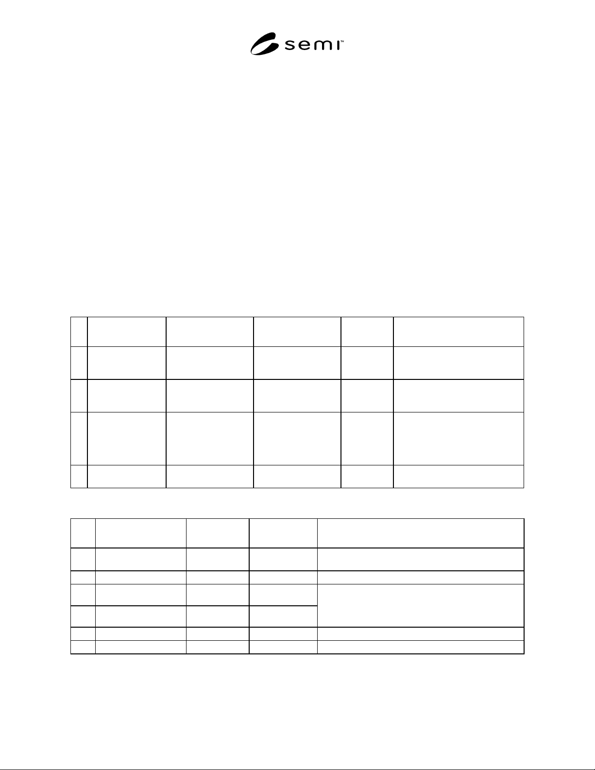
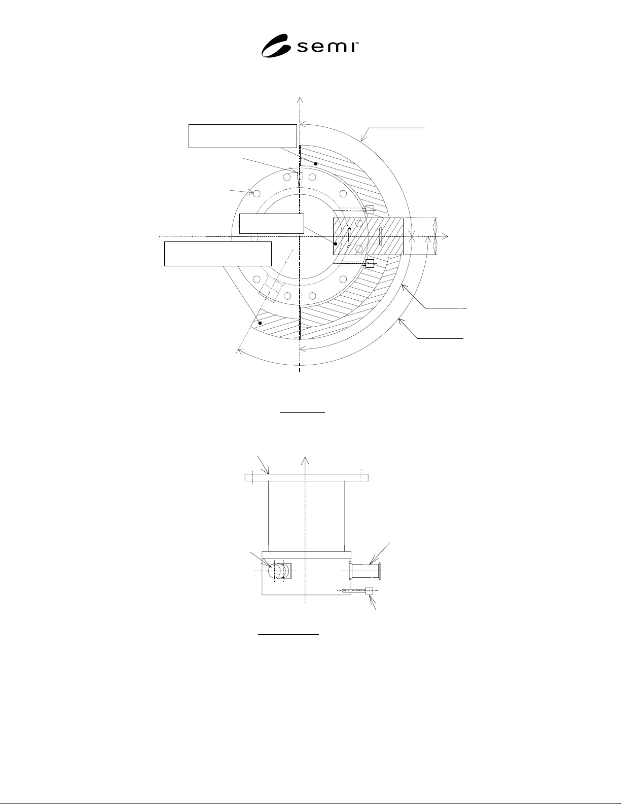
6.1.1 Table 1 specifies the required TMP connector
type and size by flange/port. Axial orientation and
position of the connectors are specified in Table 2 and
Figure 2. Port and connector positions shall be at the
periphery of the pump. Put inlet port on the z-axis and
the outlet port on the x-axis. Other connector locations
are specified by the angle between the x-axis and the
center of the connector.
Table 1 Mechanical Connectors
No. Items Connector Type Connector Size Referenced
Standard
Remarks
1 Inlet flange ISO bolted flange Connector dimensions
should be based on the
referenced standard
ISO 1609 A port flange which connects the
pump to a process tool to evacuate
gases.
2 Outlet flange ISO KF flange Connector dimensions
should be based on the
referenced standard
ISO 2861-1 A port flange which connects the
pump to the DRP (Dry Pump).
3 Purge gas port ISO KF flange Size 10 or 16 connector ISO 2861-1 A connection port used to supply
inert gas, typically N
2
, to the pump.
The purge gas protects the inside of
the pump from corrosion due to
process gases.
4 Cooling water port ISO taper pipe thread
(female on pump side)
1/4" or 3/8" ISO 7/1 A connection port to supply water
used to keep the pump cool.
Table 2 Connector Locations
No. Items Connector
Location
Connector Angle
(degrees)
Remarks
1 Inlet flange z-axis Flange bolt holes shall be symmetrically located at equal
distance from the center line of the outlet flange.
2 Outlet flange transverse
0°
3 Purge gas port transverse
- 90° to + 90°
4 Cooling water port transverse
- 90° to + 90°
The forbidden area shall be symmetrically located at
equal distances from the center of the outlet flange.
Distance from the x-axis shall be more than 1.5 times the
nominal bore of the outlet flange.
5 Electrical connections transverse
0° to -120°
6 Other ports transverse
- 90° to + 90°
SEMI E74-0301 © SEMI 1998, 20013
D: nominal bore of the outlet flange
Top view
1.5D
1.5D
X axis
the area for the purge gas inlet
& the cooling water connectors
Purge gas
inlet
bolt holes
the area
for the electrical connectors
Y axis
the forbitten area
for installation
0 to –120 deg
0 to –90 deg
0 to +90 deg
Inlet flange
Outlet flange
electrical
connector(s)
Cooling water
connectors
Side view
Z axis
Figure 2
Connector Locations
SEMI E74-0301 © SEMI 1998, 2001 4
6.2 Electrical Interfaces
6.2.1 Control Signals
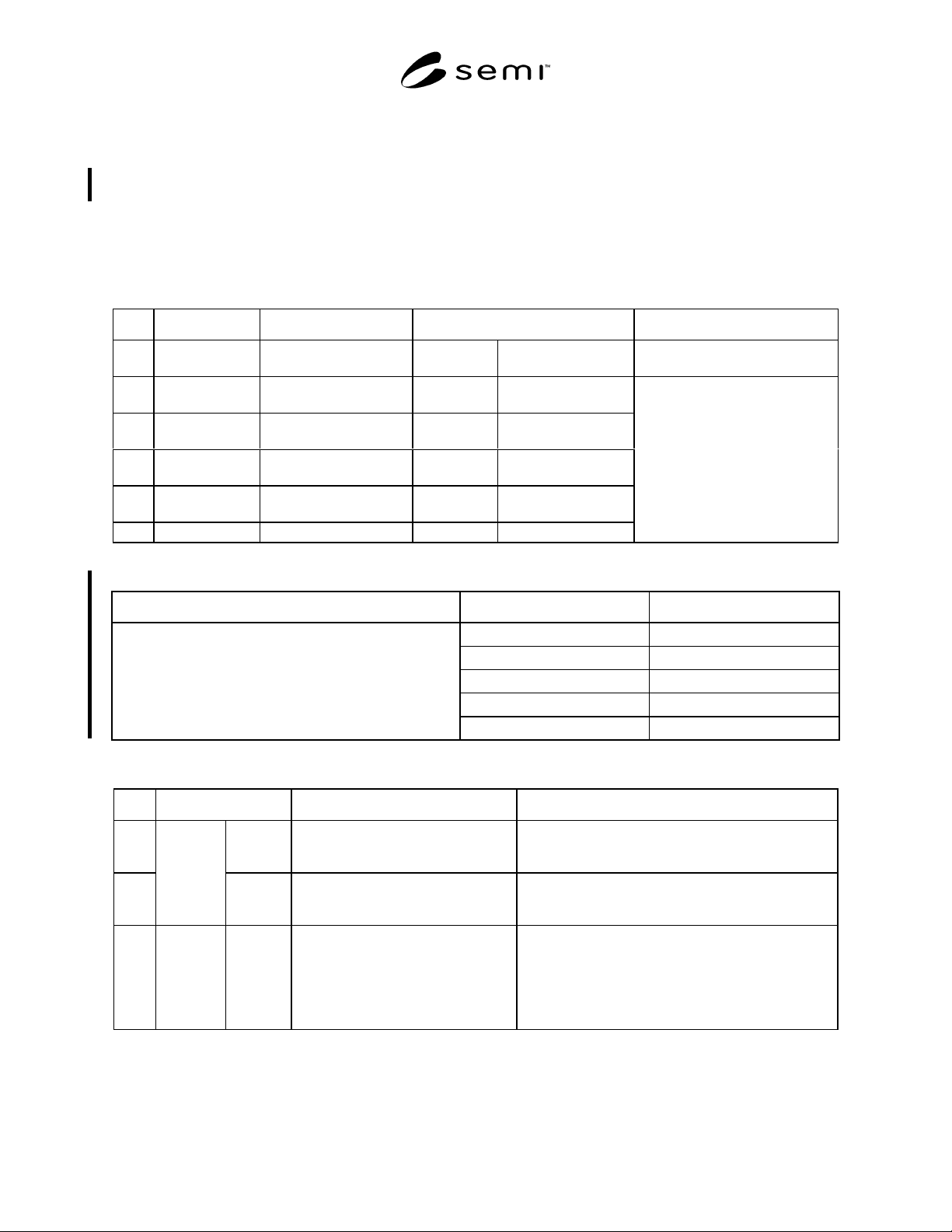
6.2.1.1 Table 3.1 specifies the required TMP control signals. In cases where TMP are backed up by battery or
regeneration power while input power failure, the status of output signals follows Table 3.2. Table 4 and Figure 3
specify the required response time for TMP control signals. Table 5 specifies the required power and contacts for
TMP control signals. Tables 6 and 7 and Figure 4 specify the required connector and pin assignments for TMP
control signals.
Table 3.1 I/O Signals
No. Signal Name Direction Type Remarks
1 Start (Run)/Stop Input signal to Pump Alternate Pump runs when
closed
2 Acceleration Output signal from Pump Alternate Close during
acceleration
3 Normal operation Output signal from Pump Alternate Close during normal
operation
4 Deceleration Output signal from Pump Alternate Close during
deceleration
5 Remote/Local Output signal from Pump Alternate Close during remote
operation
6 Pump Alarm Output signal from Pump Alternate Open at alarm
Running status signals
When input power is OFF, output
status signals should become open
(normally open).
Table 3.2 Status of output signals during back up operation mode
Status of pump Signal Name Status of signals
Acceleration Open
Normal operation Open
Deceleration Close
Remote/Local Close during remote operation
During back up operation mode
Pump alarm Open
Table 4 Response Time and Timing for Signals
No. Items Acceptable Response Time Remarks
1 Input
Power
ON
Under 10 seconds
After input power turns on
Objects
All status signals shall be ready.
2
Response
Time
Control
Signals
Under 2 seconds
After receiving a signal
Objects
Start signal (input) ->> Acceleration (output)
Stop signal (input) ->> Deceleration (output)
3 Timing Running
status
signals
Under 50 milliseconds
Acceptable delay and/or dead time in a
moment of shift of the running status
Under 50 milliseconds
Acceptable overlapped time in a
moment of shift of the running status
Objects (Example)
Normal ->> Deceleration
The running status signals of alarm and remote/local
can be overlapped with other signals.