semi合集-English.pdf - 第4862页
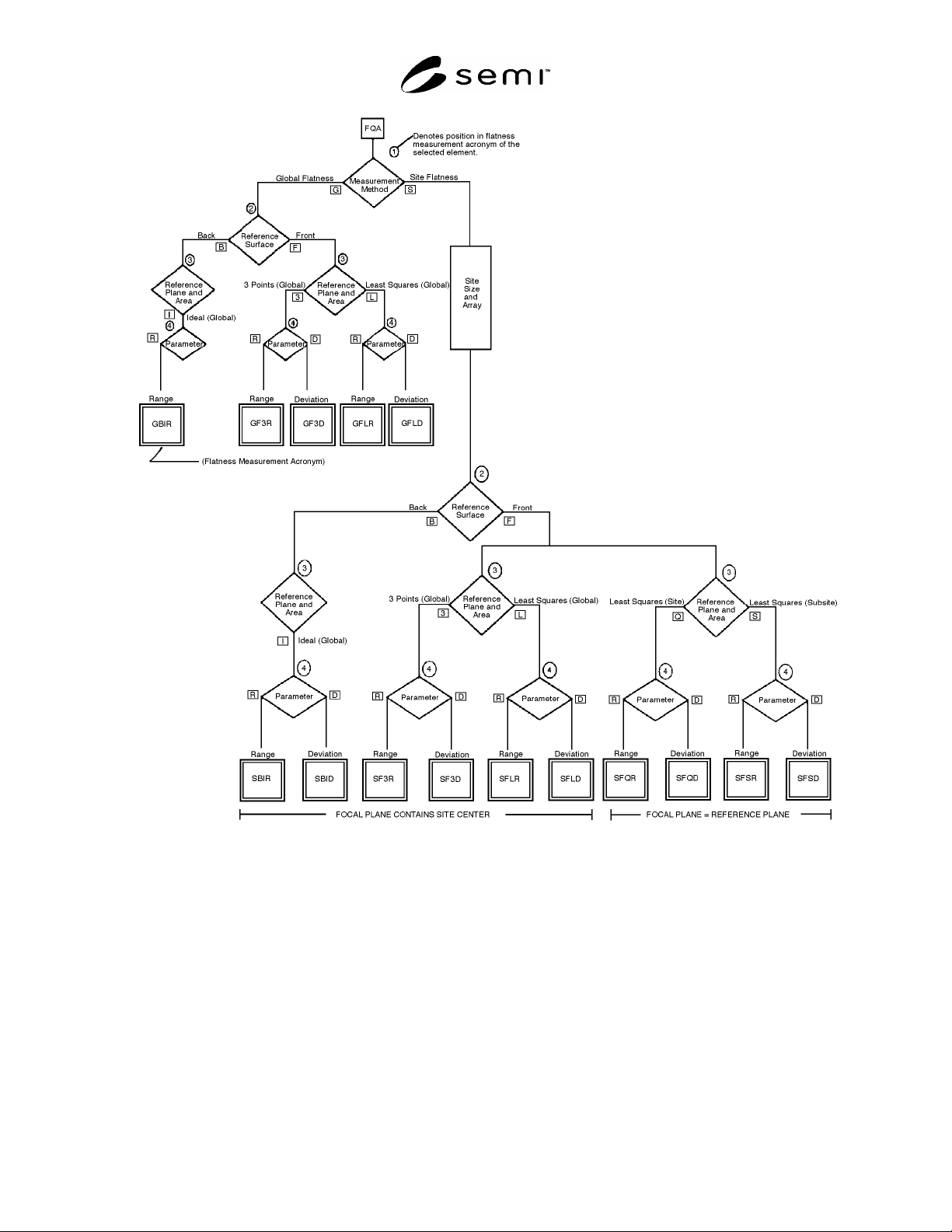
SEMI M1-0305 © SEMI 1978, 2005 38 Figure A1-1 Flatness Decision Tree A1-2.5.2 For site flatness m easurements, any of the above three planes [(1) , (3), or (L)] may be suitable or, if th e wafer is regimballed once at ea…

SEMI M1-0305 © SEMI 1978, 2005 37
APPENDIX 1
FLATNESS DECISION TREE
NOTICE: The material in this appendix is an official part of M1. Approval was by full letter ballot
procedures with publication authorized by the NA Regional Standards Committee on October 21, 1999.
A1-1 Scope
A1-1.1 The increasing complexity of integrated circuits and the reduction in design rule dimensions place new
demands on the characterization of wafer surface geometry. Various high resolution optical lithographic systems
have very limited depth of field and use a variety of methods to hold the wafer, to establish the focal plane, and to
position the wafer relative to the focal plane during exposure. These varying focusing and location methods differ
enough to make a single, simple flatness criterion (such as global TIR) ineffective in predicting successful or
unsuccessful lithography in all cases.
A1-1.2 To clarify the requirements for wafer flatness characterization for the various classes of lithographic
equipment, the decision tree depicted in Figure A1-1 has been developed. This tree gives an orderly procedure for
selecting the various parameters that must be specified if wafer flatness is specified.
A1-1.3 In this tree, it is assumed that the focal point is the site center for all parameters, except for SFQD, SFQR,
SFSD, and SFSR, where the focal plane is identical to the reference plane. Most flatness characterization systems
employ this convention. However, a number of photolithographic aligners use slightly different conventions for
determining the focal plane. Currently, the difference between the centerpoint and other focusing conventions has
not been quantified, but it is presumed to be insignificant for material characterization purposes.
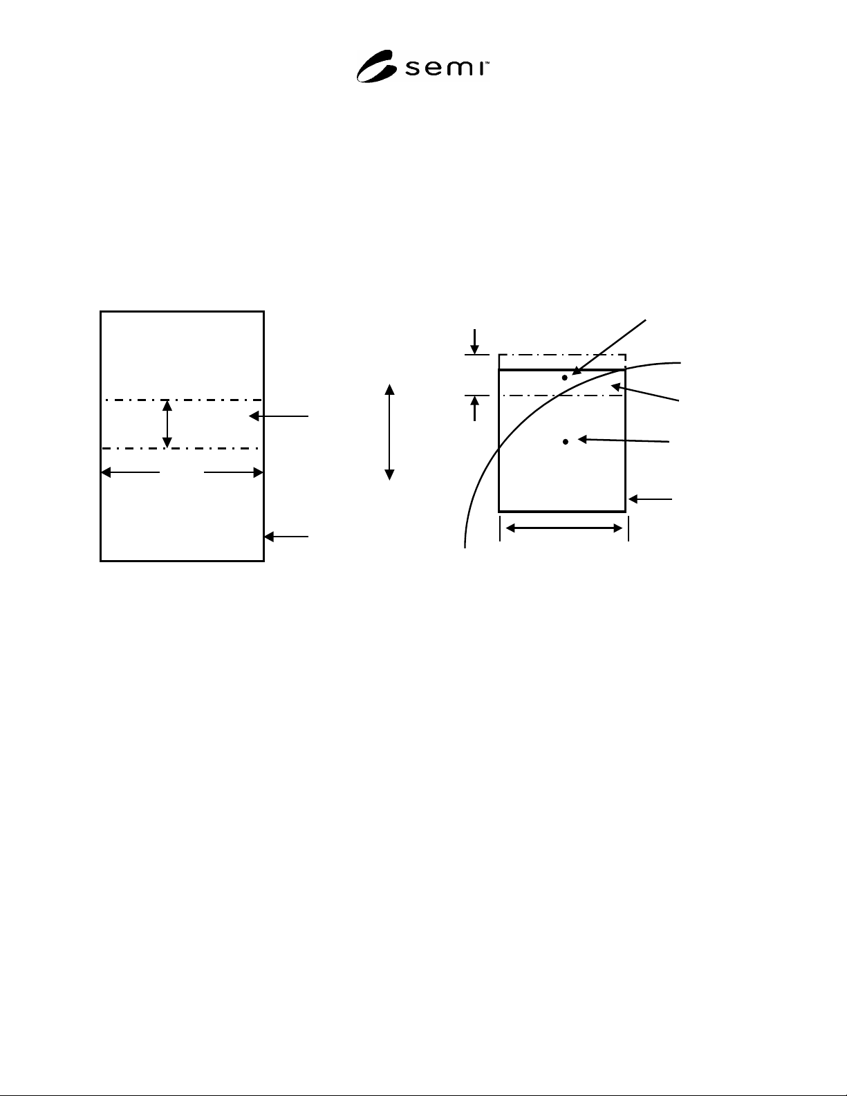
A1-1.4 For sites to be included in the measurement, the site center must lie within the Flatness Quality Area
(FQA). For subsites (se Figure A1-2) to be included in the measurement, the subsite center must lie within a site
whose center is within the FQA and some of the subsite must lie within the FQA (see Figure A1-3).
A1-2 Use of the Flatness Decision Tree
A1-2.1 In the decision tree, there are decision blocks, shown as diamonds, whose use requires some knowledge of
the lithographic tool to be used. The rectangular blocks require information to be furnished; this information is
dependent on the device layout and the manufacturing procedures to be employed (such as dedicated or mixed
aligner use).
A1-2.2 Step 1 — Select the Fixed Quality Area (FQA): Decide on and specify the nominal edge exclusion, EE,
which defines the FQA. (See Figure 1.)
A1-2.3 Step 2 — Choose the Measurement Method: Choose global flatness (G) if the lithographic tool uses a single,
global exposure of the wafer, or choose site flatness (S) if the lithographic tool steps across the wafer, exposing only
a portion of the wafer at a time.
A1-2.3.1 If global flatness is chosen, proceed to Step 3. If site flatness is chosen, it is also necessary to specify site
size (related to exposure area dimensions) and site array (including (a) number of sites, (b) location of sites relative
to the center of the FQA and to each other, as in an offset or bricklaying pattern, and (c) whether or not partial sites
are to be excluded).
A1-2.4 Step 3 — Choose the Reference Surface: Choose front surface (F) or back surface (B), depending on
whether the lithographic tool is referenced to the front or back surface.
A1-2.5 Step 4 — Choose the Reference Plane and Area:
A1-2.5.1 For global flatness measurements, a global reference plane is appropriate. If the lithographic tool is
referenced to the back surface, an ideal plane (I) defined by the chuck which holds the wafer is appropriate. If the
lithographic tool is referenced to the front surface, either a 3-point plane (3) defined by three points equally spaced
about the edge of the front surface of the wafer or a plane defined by the least squares fit to the front surface (L) may
be appropriate. The 3-point plane is appropriate if the lithographic tool holds the wafer in this fashion and does not
allow interactive gimbaling of the wafer, while the least squares plane is appropriate if the lithographic tool allows
interactive gimbaling of the wafer.
SEMI M1-0305 © SEMI 1978, 2005 38
Figure A1-1
Flatness Decision Tree
A1-2.5.2 For site flatness measurements, any of the above three planes [(1), (3), or (L)] may be suitable or, if the
wafer is regimballed once at each site, a site least squares reference plane (Q) may be appropriate or, if the wafer is
regimballed more than once at each site, a subsite least squares reference plane (S) may be appropriate.
A1-2.6 Step 5 — Choose the Measurement Parameter: Choose either TIR, also known as range (R), or FPD, also
known as deviation (D). In the case of site measurements, it is possible to specify the maximum value of (R) or (D)
or the percentage of the sites (or FQA) which have an (R) or (D) less than some specified value.
A1-2.7 The codes in parentheses in Steps 2 through 5 may be used to form a code which uniquely defines the
measurement technique as follows:
Position 1: Measurement Method (G) or (S),
Position 2: Reference Surface (F) or (B),
SEMI M1-0305 © SEMI 1978, 2005 39
Position 3: Reference Plane and Area (I), (3), (L), (Q), or (S), and
Position 4: Measurement Parameter (R) or (D).
A1-2.7.1 Stating this code, the numerical values for the FQA parameters (and, if required, information on site size
and array), and the numerical limit for the measurement parameter provides enough information to describe the
measurement and provide numerical limits.
A1-3 Future Developments
A1-3.1 As noted above, there may be specific systems which are not exactly described by one of the branch ends on
this decision tree. This tree is an approximation of the more complete one which would describe all existing and
possible lithographic technologies.
Lss
Wss = 8 mm
Subsite
Site
Scan Direction = Y
Lss
Wss
FQA
Site Center
Subsite Center
Site
Subsite area
within FQA
Figure A1-2
Scanner Site and Subsite Flatness Elements
Figure A1-3
Subsite Center near Boundaries of Site and FQA