semi合集-English.pdf - 第4094页
SEMI F58-1000 © SEMI 2000 4 9 Reporting Results 9.1 Co mplete m o isture response c u r ve s for all test syste ms and relevant te st blanks should b e include d. A summary s heet may compare systems in terms of “ind uct…

SEMI F58-1000 © SEMI 20003
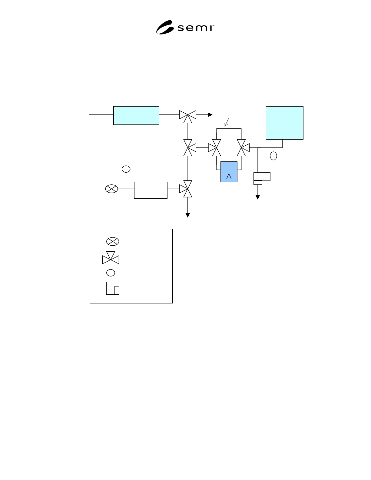
be such that some flow can be maintained through the
bypass loop and the test system simultaneously as well
as through each separately. Use of pneumatic valves to
facilitate rapid and simultaneous switching is
recommended.
7.4.2 Other arrangements than that s hown may also be
used. The moisture pulse generator should be designed
so as to give the fastest possible response of the blank
to a change in input moisture level.
7.5 Temperature Control and Measurement — A
stable temperature during the test is of critical import-
ance. The test system shall be kept at 30ºC. TESTS AT
DIFFERENT TEMPERATURES CANNOT BE
COMPARED. Ideally, the blank and test system should
be maintained in a temperature-controlled chamber.
However, if this is impractical, a heating tape can be
used. Temperature control should be to ± 1ºC. A
continuous record of temperature during the test shall
be maintained.
8 Procedure
8.1 Blank Tests — A blank test sha ll be carried out
after each calibration. If initial dry-down testing of
system is not of interest, the initial dry-down test of the
test blank may be omitted and the test blank brought to
equilibrium with zero gas in whatever manner is most
convenient, except that the test blank should not be
heated above 200ºC. Permanent changes in moisture
interaction have been observed at temperatures above
this level.
8.1.1 Initial Dry-down — Start the experiment with the
blank in place of the test system and a flow of dry gas
through the APIMS. The APIMS output should be at
equilibrium with the lowest moisture level of interest,
and in any case no higher than 200 ppt.
8.1.1.1 Switch the gas flow to pass pri marily through
the bypass loop while maintaining a small flow through
the test blank. Remove the test blank completely from
the system. If a glove box or other such enclosure is
used, do not remove the test blank from the glove box.
Immediately reconnect the test blank to V
4
, leaving it
disconnected from V
5
. Allow dry nitrogen to flow
through the test blank for five minutes to purge the air
from inside before reconnecting to V
5
. Switch the gas to
flow only through the blank and not through the bypass
loop. The APIMS will show an increase in moisture
concentration. Record the APIMS output until it
reaches 800 ppt or 48 hours, whichever is less.
8.1.1.2 Repeat the above test twice for a total of three
data sets.
8.2 Tests on Actual Test System
8.2.1 Initial Dry-down — This porti on of the test is
designed to determine the quantity of removable
moisture on the wetted surfaces of the system in the
condition in which it is typically supplied. Thus, the
results of this test will reflect, by design, any
precautions which the supplier has taken to remove
moisture and maintain its dryness during shipping.
8.2.1.1 Start the test as in Section 8.1. 1. The test
system should not be unpacked until after the APIMS
has equilibrated with the background moisture level. If
a glove box or other such enclosure is used, unpack the
system in the glove box. Switch the dry nitrogen flow
to pass through the bypass loop while maintaining a
small flow through the test blank. Bake the sample line
to APIMS at 170°C for 10 min and the APIMS ion
chamber at 150°C for 10 min. Undo the final layer of
packing and any shipping caps or plugs on the system at
this point. Remove the sample blank and connect the
test system to valve V
4
as quickly as possible. Ensure
that the gas lines going to APIMS will be under N
2
purge during the removal of test blank and installation
of test system. Allow the dry nitrogen flow to purge out
any ambient air in the system for five minutes, then
connect the system to V
5
. Switch the gas to flow (1.2
slpm) only through the test system and not through the
bypass loop. The APIMS will show an increase in
moisture concentration. Record the APIMS output until
it reaches 200 ppt or for 24–48 hours, whichever is less.
8.2.1.2 After 24–48 hours, the initial d ry-down part of
the test can be terminated. Remove the filters from the
test system and install special spool pieces. This is done
since filters have a large surface area and would
dominate the dry-down performance.
8.2.2 Moisture Input Test — Flow 1 .2 slpm of dry
nitrogen gas (200 ppt moisture) through appropriate
process channels of the test system. Connect the outlet
of the gas panel to the sample line connecting to the
APIMS. Bake the appropriate process channels using
heater tapes at 60°C for 12 h to remove atmospheric
contamination.
8.2.2.1 At the conclusion of baking, equilibrate the test
system to 30°C. Bake the sample line at 170°C for 10
min and ion source of APIMS at 150°C for 10 min.
Perform a leak check at the inlet and outlet connections
of the test system using 1% methane gas in nitrogen,
after warming up the APIMS for 30 min. Switch the
input gas to nitrogen with 200 ppb moisture (by
switching valves V
1
, V
2
, and V
3
simultaneously, if the
arrangement shown in Figure 1 is used) while recording
the APIMS response. Maintain this input for 20 min
and then switch the input gas to dry nitrogen (200 ppt
moisture) and monitor the dry-down.
SEMI F58-1000 © SEMI 2000 4
9 Reporting Results
9.1 Complete moisture response curves for all test
systems and relevant test blanks should be included. A
summary sheet may compare systems in terms of
“induction time,” peak height, and/or decay time
(detected moisture concentrations may be plotted as a
function of time for the test systems). Temperature,
pressure, and flow measurements, and as complete a
record as possible of all experimental variables should
be noted.
Regulator
3-port Valve
Pressure gauge/
Transducer
MFC
Dryer +
Filter
Moisture
Generator
APIMS
P1
Regulator
V2
V3
V4
V5
MFC
Test system
(At 30°C)
To vent
To vent
UHP N
2
Bypass loop
UHP N
2
V1
P2
To vent
Figure 1
APIMS Moisture Test Schematic
NOTICE: SEMI makes no warranties or representations as to the suitability of the standards set forth herein for any
particular application. The determination of the suitability of the standard is solely the responsibility of the user.
Users are cautioned to refer to manufacturer’s instructions, product labels, product data sheets, and other relevant
literature with respect to any materials mentioned herein. These standards are subject to change without notice.
The user’s attention is called to the possibility that compliance with this standard may require use of copyrighted
material or of an invention covered by patent rights. By publication of this standard, SEMI takes no position
respecting the validity of any patent rights or copyrights asserted in connection with any item mentioned in this
standard. Users of this standard are expressly advised that determination of any such patent rights or copyrights and
the risk of infringement of such rights, are entirely their own responsibility.
Copyright by SEMI® (Semiconductor Equipment and Materials
International), 3081 Zanker Road, San Jose, CA 95134. Reproduction o
f
the contents in whole or in part is forbidden without express written
consent of SEMI.

SEMI F59-0302 © SEMI 2000, 2002 1
SEMI F59-0302
TEST METHOD FOR DETERMINATION OF FILTER OR GAS SYSTEM
FLOW PRESSURE DROP CURVES
This test method was technically approved by the Global Facilities Committee and is the direct responsibility
of the North American Facilities Committee. Current edition aproved by the North American Regional
Standards Committee on November 27, 2001. Initially available at www.semi.org December 2001; to be
published March 2002. Originally published October 2000.
NOTE: This document was entirely rewritten for
publication in 2002.
1 Purpose
1.1 The purpose of this document is to define a method
for testing filters or gas systems being considered for
installation into a high-purity gas distribution system or
on semiconductor manufacturing equipment,
respectively. Application of this test method is
expected to yield comparable data among filters or gas
systems.
1.2 This document establishes a test method for
preparing a pressure drop versus flow rate curves for
filters and gas systems.
2 Scope
2.1 This procedure applies to clean filters including
those cartridges of metal, ceramic and membrane
construction. The pressure drops for integral
housing/cartridge combination units are determined as a
single set of values. For housings with removable filter
cartridges, the flow curves of the housing and
housing/cartridge combination are determined
separately.
2.2 This procedure applies to high-purity gas systems.
This procedure applies to face-seal, surface mount—
modular, and monolithic integrated gas systems.
2.3 This standard does not purport to address safety
issues, if any, associated with its use. It is the
responsibility of the users of this standard to establish
appropriate and safety health practices and determine
the applicability of regulatory limitations prior to use.
3 Limitations
3.1 For separable filtration units, a single cartridge
pressure drop value cannot be combined to give the
pressure drop value for an extended length cartridge,
because of the limitations imposed by a common outlet
port for the assembly.
3.2 This method is written with the assumption that the
operator understands the use of the apparatus at a level
equivalent to six months of experience.
3.3 This method is written to test a filter under normal
operating conditions. It does not prescribe a procedure
for reverse flow testing since operation of the filter in
this manner is not recommended by the manufacturers.
3.4 Components that induce line pressure changes on a
system such as pressure regulators, and MFCs are not
considered in this test method.
3.5 Proper flow of low vapor pressure gases can be
effected by small pressure drops and may need to be
evaluated independently.
4 Referenced Standards
NOTE 1: As listed or revised, all documents cited shall be
the latest publications of adopted standards.
4.1 ASME Performance Test Code PTC 19.5, 1972
“Applications.” Part II of “Fluid Meters, Interim
Supplement on Instruments and Apparatus.”
1
5 Terminology
5.1 Abbreviations and Acronyms
5.1.1 CDA clean, dry air
5.1.2 °C degrees Celsius
5.1.3 DUT device under test
5.1.4 kg kilogram
5.1.5 kPa kilopascals, (kNm
-2
)
5.1.6 m meter
5.1.7 MFC mass flow controller
5.1.8 N Newton (kg m/s
2
)
5.1.9 P pressure in kiloPascal (kPa)
5.1.10 POC — point of connection
5.1.11 psi pounds per square inch
5.1.12 psia pounds per square inch absolute
5.1.13 psid pounds per square inch differential
5.1.14 psig pounds per square inch gauge
1 American Society of Mechanical Engineers (ASME) International,
3 Park Avenue, New York, NY 10016-5990