semi合集-English.pdf - 第449页
SEMI E64-0600 © SEMI 1997, 2005 4 RELATED INFORMATION 1 APPLICATION NOTES NOTICE : This rel ated inform ation is not an official part of SEMI E64 but was approved for publication by full letter ballot procedures. R1-1 Th…
SEMI E64-0600 © SEMI 1997, 2005 3
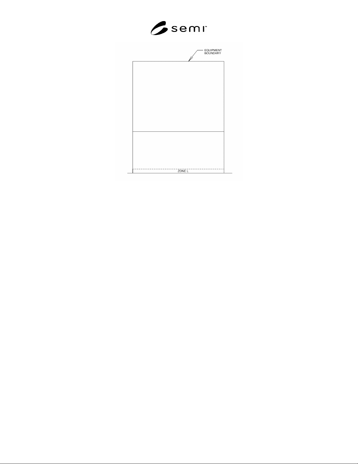
Figure 2
Front Elevation View

SEMI E64-0600 © SEMI 1997, 2005 4
RELATED INFORMATION 1
APPLICATION NOTES
NOTICE: This related information is not an official part of SEMI E64 but was approved for publication by full letter
ballot procedures.
R1-1 The intent of this standard is (1) To provide manually guided 300 mm carrier transport carts a standard
location for docking to process and other tools; and (2) To facilitate development of a rapid repeatable cart to load
port carrier transfer method or mechanism. Standardization of the size and location will allow for a modularity of the
docking interface while minimizing limits on functionality of the interface.
R1-2 Zone L is defined as an exclusion zone in tools that comply with SEMI E15.1. It is intended that the tool side
of a “cart/tool” docking interface be mounted in this zone.
R1-3 The docking interface (cart or tool side) may include all or some of the following features/functionality:
Stopping cart motion,
Dampening impact of docking,
Compliance, Lead-in guidance for cart,
Alignment of cart to docking interface, and
Securely locking position of cart during carrier transfer.
R1-4 It is likely that the alignment error and tolerance stack-up between a device in Zone L and the tool port will
not provide sufficient accuracy alone for accurate pick/placement of a carrier onto the kinematic couplings on the
load port.
R1-5 Possible sources of alignment errors are
Cleanroom floor height and level,
Cart wheels and framework,
Installation accuracy of device in Zone L, and
Stability of mounting (floor changes).
R1-6 It may be necessary to use additional alignment methods to improve accuracy of carrier placement onto the
kinematic couplings.
R1-7 It is expected that the interface device will be floor-mounted. SEMI E64 allows for automatic docking but
does not specify the means or interfaces required. Cart/interface designers may find it advantageous to add
registration features to the tool or load port which facilitate automatic docking and/or carrier transfer.
NOTE 1: Exclusion Zone L partially overlaps the installation space for the photo-coupled interface in SEMI E23. Compliance
with both standards is possible. Suppliers should be aware of both standards and design accordingly.
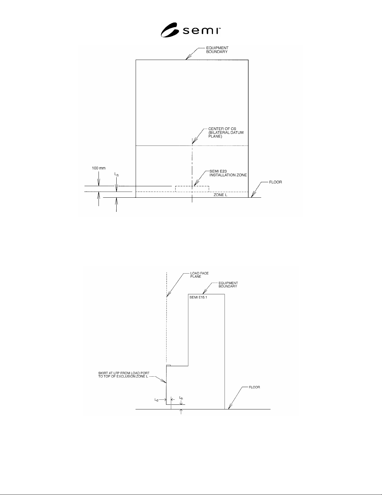
R1-8 Compatibility with SEMI E23 can be maintained by reserving the area just above Zone L for installation of
the photo-coupled I/O interface specified in SEMI E23 as shown in Figure R1-1.
R1-9 Zone L should remain clear of any physical obstructions to allow for installation of docking interface devices.
End users may require other features that occupy this space, but should be aware that this could limit cart to tool
docking solutions.
SEMI E64-0600 © SEMI 1997, 2005 5
Figure R1-1
Front Elevation View
R1-10 Note that an installed docking interface may cause a potential trip hazard as shown in Figure R1-2.
Equipment suppliers and/or docking interface suppliers may be required to eliminate the potential of this hazard
(e.g., by adding covers or shields).
Figure R1-2
Side Elevation View