semi合集-English.pdf - 第2356页
SEMI E82-0705 © SEMI 1999, 2005 52 RELATED INFORMATION 2 REQUIREMENTS FO R COMPLIANCE NOTICE : This rel ated information is not an of ficial part o f SEMI E 82, but wa s approved for publ ication by full letter ballot pr…
SEMI E82-0705 © SEMI 1999, 2005 51
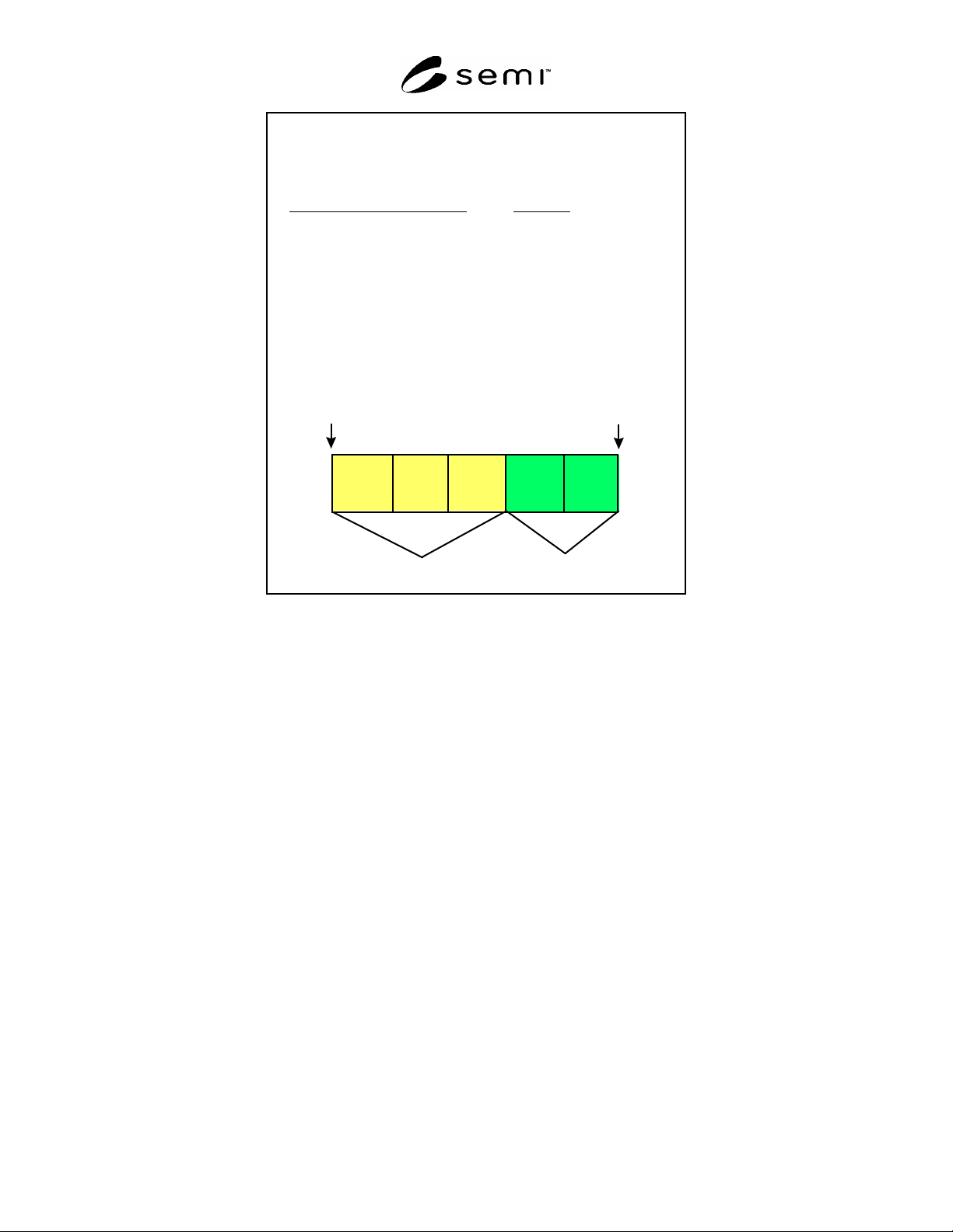
The following TRANSFER commands are
received by the TSC in top to bottom order:
TRANSFER Command
Priority
1 Normal
2 Normal
3 High
4 Normal
5 High
4 2 1 5 3
head
tail
Corresponding TSC processing queue
for outstanding TRANSFER commands :
Normal
High
Figure R1-4
TSC Priority-based FIFO TRANSFER Command Processing Example
R1-4.2 The TSC must manage the vehicles so that TRANSFER requests are queued for later service if all vehicles
are currently utilized.
R1-5 Transport System Handling and Delivery of the Transfer Unit
R1-5.1 A transfer unit must always be delivered by the same vehicle simultaneously. A transfer unit cannot be split
between multiple vehicles.

SEMI E82-0705 © SEMI 1999, 2005 52
RELATED INFORMATION 2
REQUIREMENTS FOR COMPLIANCE
NOTICE: This related information is not an official part of SEMI E82, but was approved for publication by full
letter ballot procedures.
Table R2-1 provides a checklist for IBSEM compliance.
R2-1 IBSEM Compliance Statement
Table R2-1 IBSEM Compliance Statement
Fundamental IBSEM Requirements Implemented IBSEM Compliant
TSC State Model
Yes No Yes No
Transfer Command State Model
Yes No Yes No
Vehicle State Model (optional, see ¶7.4)
Yes No Yes No
Carrier State Model
Yes No Yes No
Collection Event List
Yes No Yes No
Collection Event Data Availability
Yes No Yes No
Variable Data Items
Yes No Yes No
Variable Data Availability
Yes No Yes No
Alarm List
Yes No Yes No
Remote Command List
Yes No Yes No
Remote Command Parameters
Yes No Yes No
Remote Command Mapping
Yes No Yes No
Transfer Command Format
Yes No Yes No
System Architecture
Yes No Yes No
Traffic Management Characteristics
Yes No Yes No
Delivery of the Transfer Unit
Yes No Yes No
NOTICE: SEMI makes no warranties or representations as to the suitability of the standards set forth herein for any
particular application. The determination of the suitability of the standard is solely the responsibility of the user.
Users are cautioned to refer to manufacturer's instructions, product labels, product data sheets, and other relevant
literature, respecting any materials or equipment mentioned herein. These standards are subject to change without
notice.
By publication of this standard, Semiconductor Equipment and Materials International (SEMI) takes no position
respecting the validity of any patent rights or copyrights asserted in connection with any items mentioned in this
standard. Users of this standard are expressly advised that determination of any such patent rights or copyrights, and
the risk of infringement of such rights are entirely their own responsibility.
Copyright by SEMI® (Semiconductor Equipment and Materials
International), 3081 Zanker Road, San Jose, CA 95134. Reproduction of
the contents in whole or in part is forbidden without express written
consent of SEMI.

SEMI E84-0305 © SEMI 1999, 2005 1
SEMI E84-0305
SPECIFICATION FOR ENHANCED CARRIER HANDOFF PARALLEL I/O
INTERFACE
This specification was technically approved by the Global Physical Interfaces & Carriers Committee and is
the direct responsibility of the Japanese Physical Interfaces & Carriers Committee. Current edition approved
by the Japanese Regional Standards Committee on November 24, 2004. Initially available at www.semi.org
January 2005; to be published March 2005. Originally published June 1999; last published March 2004.
1 Purpose
1.1 Due to the migration to large wafer sizes, future semiconductor factories will use extensive automated material
handling systems (AMHS) to transfer wafer carriers, including FOUPs and open cassettes, of increasing weight. The
parallel input/output (PI/O) control signals between the production equipment and the AMHS must be better defined
for more reliable and efficient carrier handoffs (load/unload) at production equipment load ports.
1.2 The purpose of this specification is to enhance the capabilities of the parallel I/O interface defined in SEMI E23
in order to support improvements in the reliability and efficiency of carrier transfer. The enhanced capabilities
include continuous handoff, simultaneous handoff, and the capabilities of error detection on the interface.
NOTE 1: The specifications in this document shall be considered independent from the specifications in SEMI E23; therefore,
use of this specification does not require SEMI E23.
2 Scope
2.1 The scope of this specification is limited to communications associated with the material handoff operations
between the active equipment (for example, AMHS equipment including AGV, RGV and OHT) and the passive
equipment (for example, production equipment including process and metrology equipment; stockers, etc). This
scope also extends to interbay AMHS active equipment (i.e., OHS and stockers equipped with transfer devices) and
passive equipment (i.e., OHS and stockers not equipped with transfer devices). This specification defines the
enhanced parallel I/O interface signals used to handoff carriers between the production equipment and the AMHS.
Figures 1 and 2 show examples of types of AMHS equipment.
2.2 This enhanced carrier handoff parallel I/O interface specification includes:
Signal definition including load port assignment signals (¶6.1),
Carrier handoff sequence definitions and time diagrams (¶6.2),
Error indication, detection, and recovery (¶¶6.3 and 6.4),
Connector type, signal, and pin assignment (¶6.4), and
Interface sensor unit size to be located at load port defined by SEMI E15.1 (applicable for systems designed to
handle 300 mm wafer carriers).
2.3 The enhanced carrier handoff parallel I/O interface controls the handoff of a carrier to and from the passive
equipment by the active equipment. This parallel I/O interface only controls the automated handoff operation of the
carrier. The handoff is the operation in which a carrier is transferred from one piece of equipment to another. Both
the active and passive equipment manage this operation. The factory level controller (i.e., host) does not manage the
handoff operation. Figure 3 shows applications for the parallel I/O interface specified in this document.
NOTICE: This standard does not purport to address safety issues, if any, associated with its use. It is the
responsibility of the users of this standard to establish appropriate safety and health practices and determine the
applicability of regulatory or other limitations prior to use.
3 Limitations
3.1 Data for the material that is transferred (handed off) is managed through the equipment’s factory interface.
Material management by the factory level controller is outside the scope of this document.