semi合集-English.pdf - 第7705页
SEMI T9-0200 © SEMI 1998, 2004 6 Figure 3 Border Rows and Columns Figure 4 Data Matrix Code Field ECC200 – 12 Rows 26 Columns
5 SEMI T9-0200 © SEMI 1998, 2004
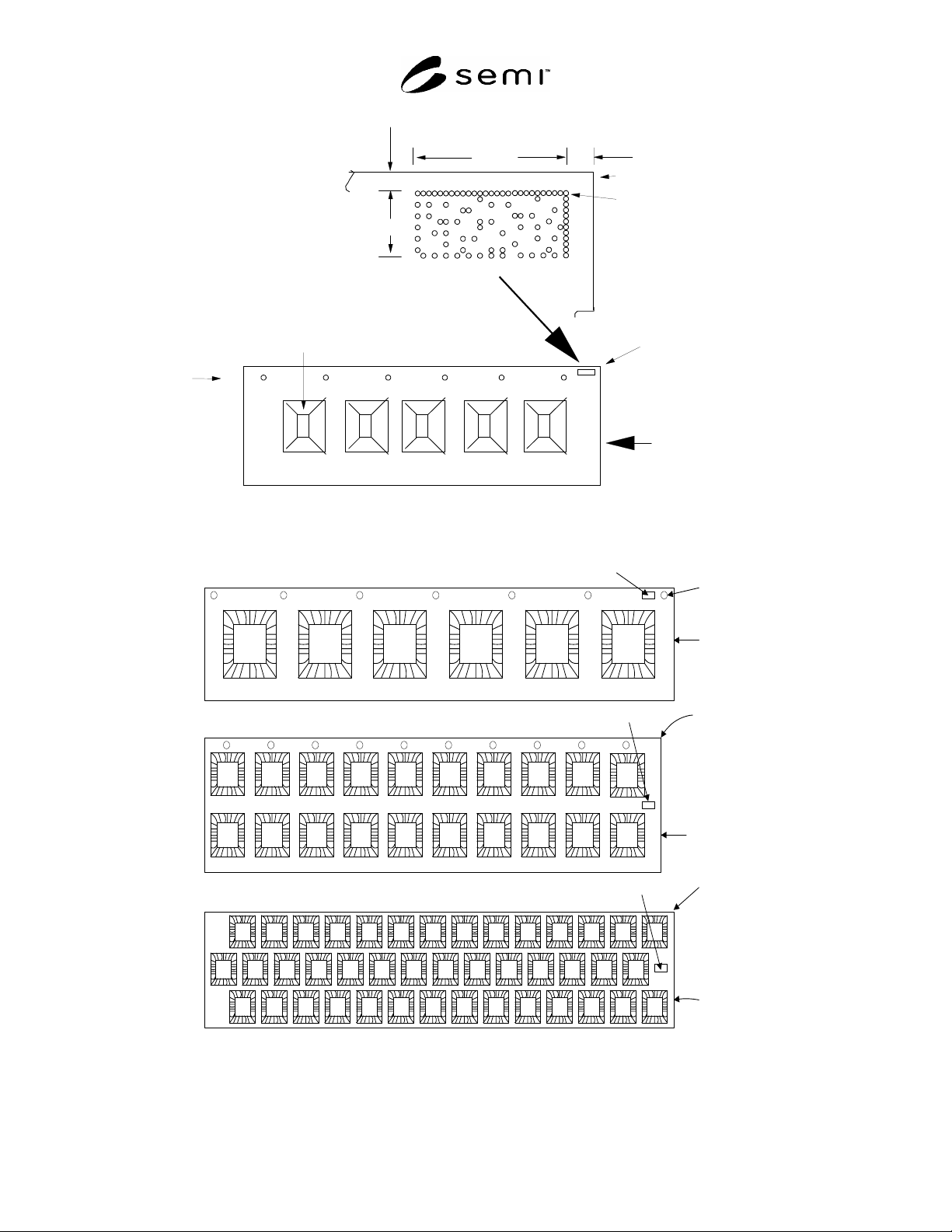
6.3.3 For the default location for the symbol, A = 0.4 mm and B = 2.5 mm.This location may not be acceptable for
all lead strips. The mark may be placed in other locations provided that the following condition is maintained:
6.3.3.1 A zone 0.3 ± 0.1 mm wide and clear of marks and other surface features is maintained around the entire data
matrix code (sometimes called “quiet zone”).
6.3.4 Refer to Figure 6 for examples of acceptable data matrix code locations on several lead-frame designs.
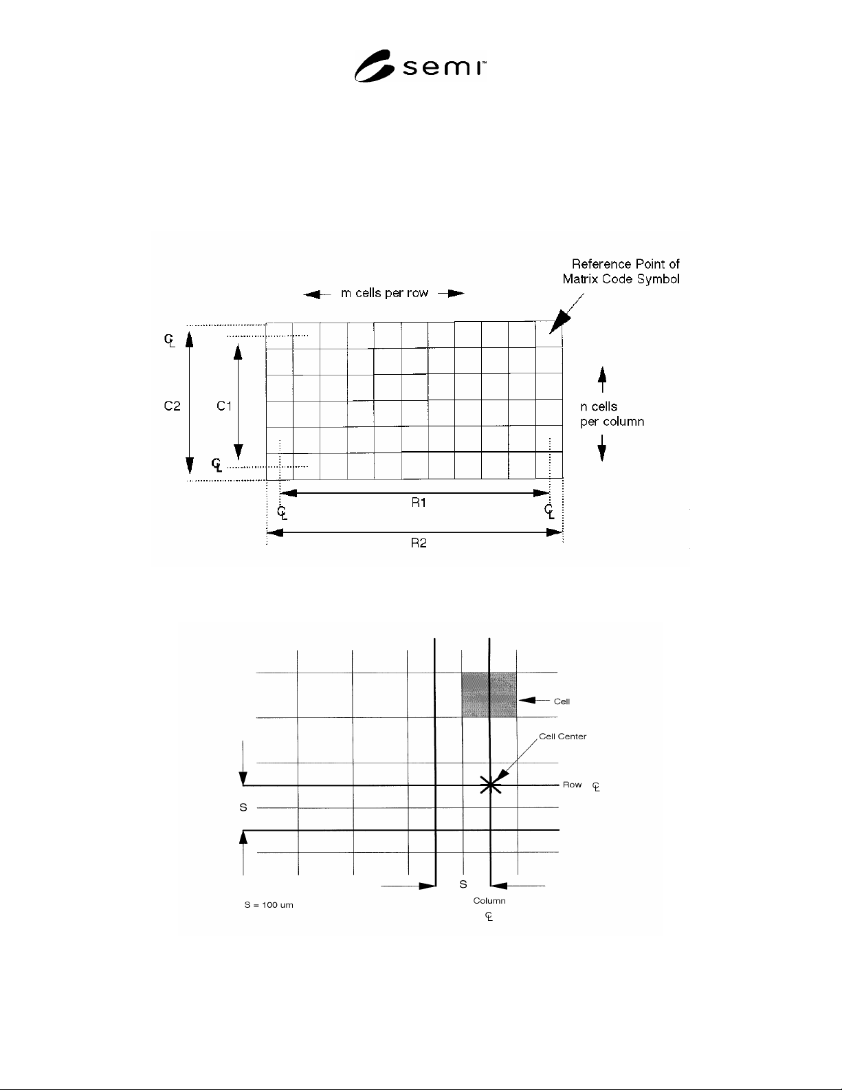
Figure 1
Data Matrix Field Dimensions
Figure 2
Data Matrix Cell Dimensions
SEMI T9-0200 © SEMI 1998, 2004 6
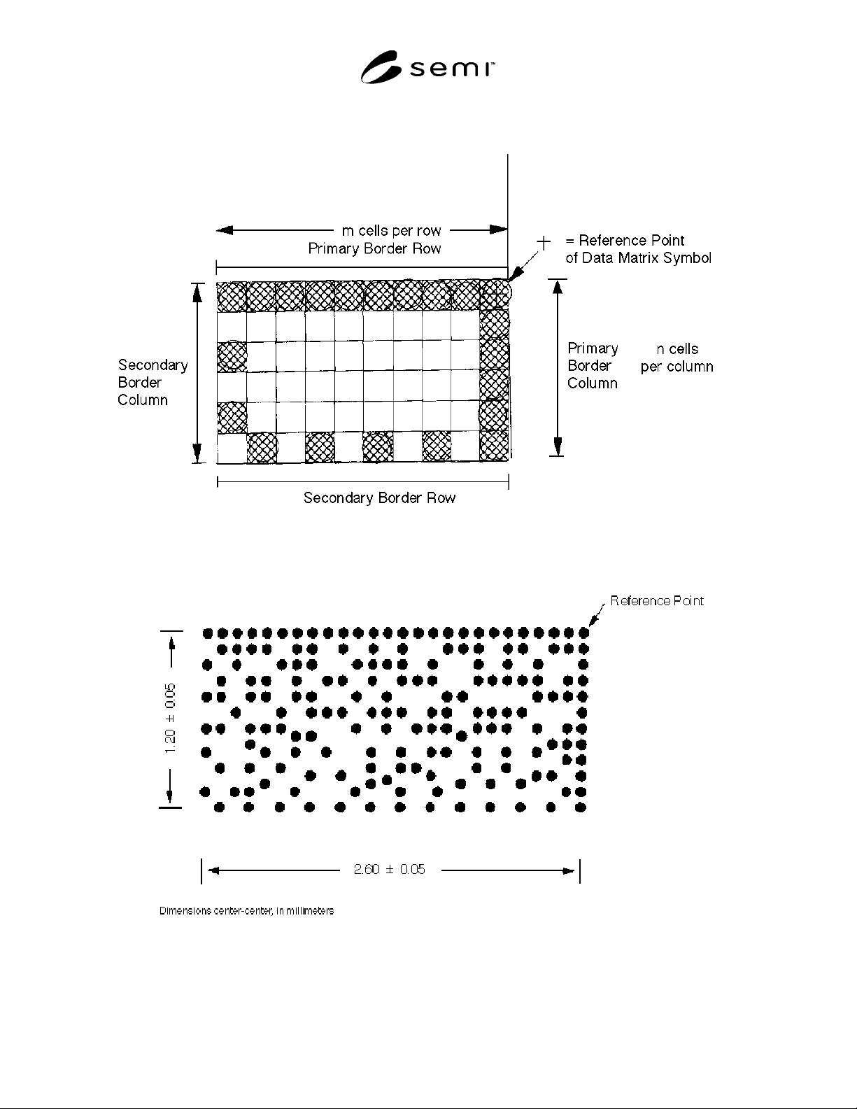
Figure 3
Border Rows and Columns
Figure 4
Data Matrix Code Field
ECC200 – 12 Rows
26 Columns
7 SEMI T9-0200 © SEMI 1998, 2004
Data Matrix ID Field
Bondin
g
Pad
Locating Holes
TOP VIEW
12 row x 26 column Field
ECC200
Simulated 22-character Message
1.2 mm
2.6 mm
0.3 mm, miminimum
2.0 mm, miminimum
Strip Rail
Strip Orientation Corner
Mark
Reference
Point
Strip Orientation Corner
Strip
Edge
Leading
(C2)
(
R2
)
Figure 5
Leadframe with Data Matrix ID Field
Strip
Leading
Edge
Strip
Orientation
Corner
Strip
Leading
Edge
Strip
Leading
Edge
Data Matrix Field
Data Matrix Field
Data Matrix Field
Strip
Orientation
Corner
Strip
Orientation
Corner
Figure 6
Alternate Lead-Frame Configurations and
Suggested Data Matrix Field Locations