semi合集-English.pdf - 第5153页
SEMI M31-0705 © SEMI 1998, 2005 13 x 42 = 50 ± 1 x 41 = 30 ± 1 y 45 =65.3± 1 y 47 58 x 44 53 facia l datum plane bilateral datum plane front side of the carrier where waf ers are accesse d y 41 = 30 ± 1 y 46 = 71 …
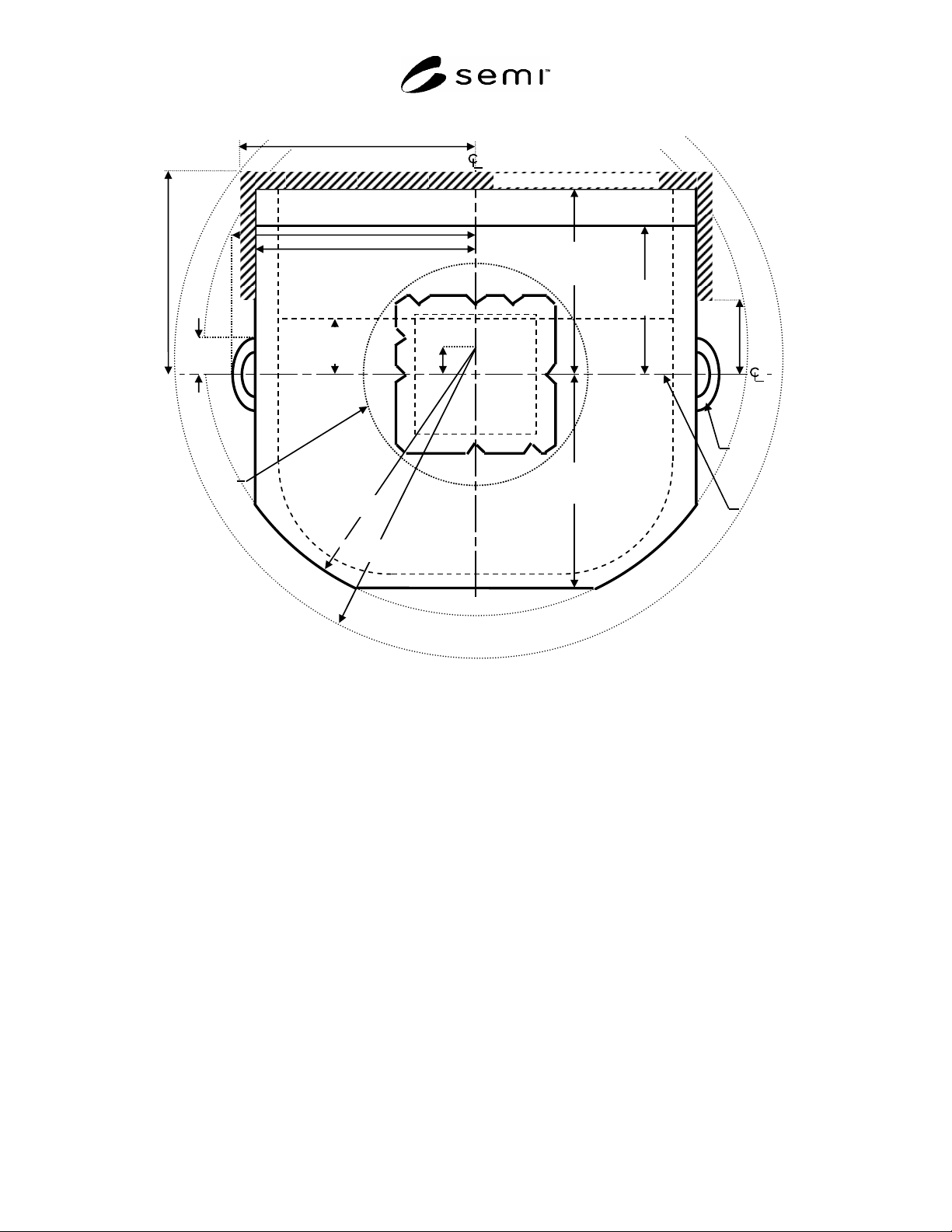
SEMI M31-0705 © SEMI 1998, 2005 12
human
handle
(optional)
y53
190
y52 =
165.5 ± 0.5 mm
(6.52 ± 0.02 in.)
bilateral
datum plane
front side of the FOSB where wafers are accessed
y51
50
y50
130
x50 215 (at human handle)
x53 195 (elsewhere)
r67 240
facial
datum
plane
y40
116
y67
= 25
detail in
Figure 12
r68 271
x81 215
y82
191
y81
30
x81 215
Manual door exclusion zone
Figure 10
Top View of FOSB
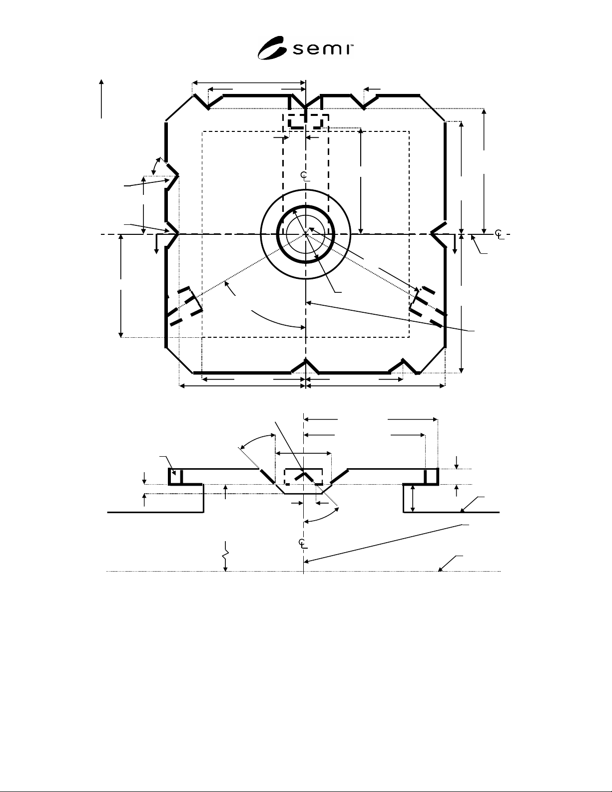
SEMI M31-0705 © SEMI 1998, 2005 13
x42 = 50 ± 1
x41 = 30 ± 1
y45
=65.3± 1
y47
58
x44
53
facial
datum
plane
bilateral
datum
plane
front side of
the carrier
where wafers
are accessed
y41 = 30 ± 1
y46 =
71 ± 1
x43 = 50 ± 1
x47
58
(16x)
= 45
± 0.5°
positio
n notch
orientation
notch
x46 = 71 ± 1
x45 =
65.3 ± 1
y44 53
d63
=35 + 0.9 / -0.1
y68
55
x69 = 7.6 ± 0.1
= 60°
r63
66
top
of box
bilateral
datum plane
horizontal
datum plane
z47
= 210 (330)
[253 (373)]
± 1
position notch
d63
=35 +0.9 / -0.1
cross-
section
above
x69 = 7.6 ± 0.1
= 45 ± 1°
= 52 ± 1°
x45 = 65.3 ± 1
x46 = 71 ± 1
z49 8
z48
15
(numbers in parentheses are for 25-wafer boxes, if different)
[numbers in square brackets are for removable cassettes, if different]
z50
5
r59
6
Figure 11
Top Robotic Handling Flange
SEMI M31-0705 © SEMI 1998, 2005 14
r13
2.5
y52 =
165.5 ± 0.5 mm
(6.52 ± 0.02 in.)
facial
datum
plane
x53 195
bilateral
datum
plane
y
53
190
front side of the FOSB where wafers are accessed
kinematic
coupling
pin
info pad D
info pad B
info pad C
info pad A
y17
= 27.5
x13 = 88.5
y10
= 123.5
y9
= 92.5
y18
= 40.2
r13
2.5
r14 7.5
r17 10
r13
2.5
x8 = 12.5
human
handle
(optional)
y19
= 61.1
x21 = 30
x22 = 70
x
57 180
d65 = 10 ± 0.5
x
65
= 187.5
carrier
sensing
pads
(height
z2 2
mm)
x
50 215
(
at human handle
)
x56 = 194.75 ± 0.25 (at bottom rail)
x14 = 118.5
x17 = 17.5
y40
116
y58
75
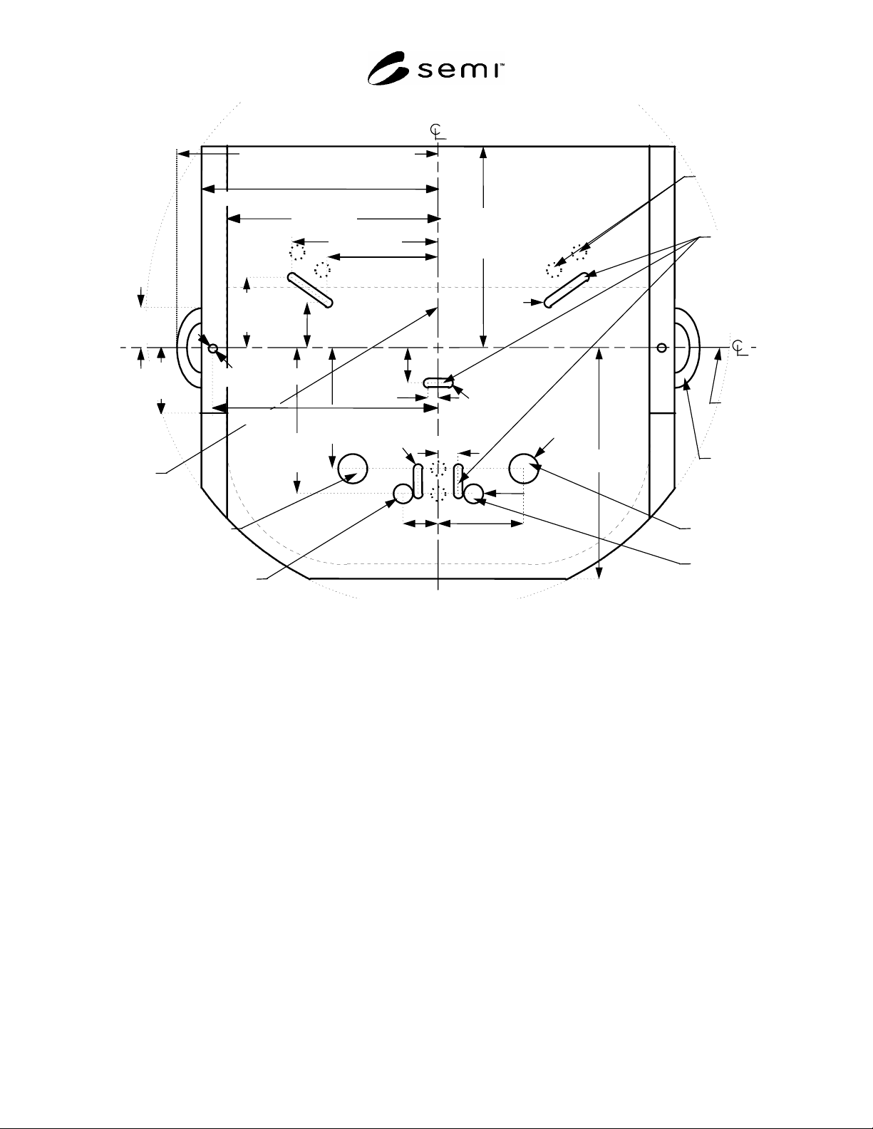
NOTE: Info pad height (z2, z26) is described in table 3.
Figure 12
Bottom View of FOSB
5.14 Retaining Features — Figure 13 and 14 show two features on the bottom of the FOSB that may be used for
retaining the FOSB onto the kinematic couplings. Retaining features are option for the FOSB with manual door,
however those are required for the FOSB with automated-shippable door. This may be needed to prevent the FOSB
from being knocked off the kinematic couplings by the action of pushing the FOSB against the front-opening
interface. The front retaining feature contains a ramp that a wheel might roll up while the FOSB is being pushed
toward the front-opening interface. The arm with the wheel (not specified here) then holds the FOSB down on the
kinematic couplings. The center retaining feature consists of an oblong slot with a chamber above it. The FOSB can
be clamped onto the kinematic couplings by inserting an oblong head on a shaft (not specified here) through the slot
and rotating it 90° in either direction. Either retaining feature would only engage after the FOSB is fully seated on
the kinematic coupling pins. Either retaining feature must be able to withstand a force in any direction of at least f60.
It is recommended that SEMI E15.1 tool load ports be designed to accommodate the minimum hole dimensions of
the retaining features to ensure carrier interchangeability. Projections on the tool load ports that mate with the
retaining features should also not interfere with the misalignment correction function of the kinematic couplings.
5.15 Sensing Pads — As shown in Figure 12, when the FOSB is fully down on the kinematic coupling, the carrier
sensing pads must be z2 above horizontal datum plane. It is recommended that the areas surrounding all of the
carrier sensing pads be designed in conjunction with the features that mate with kinematic coupling pins so that a
mechanical sensor pin cannot interfere with the lead-in function of the kinematic couplings. Other sensing pads
(called info pads and given letter names) communicate information about the carrier. Note that since this is a bottom