semi合集-English.pdf - 第4642页
SEMI C3.51-11 01 © SEMI 1995 , 2001 2 7.1.2.4 Temperatures : Colum n Tem perature 100°C Detec tor Tempe rature 100°C 7.1.2.5 Bridge Current — 200 m A. 7.1.3 Calibration St andard — 1–10 p pm ni trogen in heli um. 7.1.3.1…
SEMI C3.51-1101 © SEMI 1995, 20011
SEMI C3.51-1101
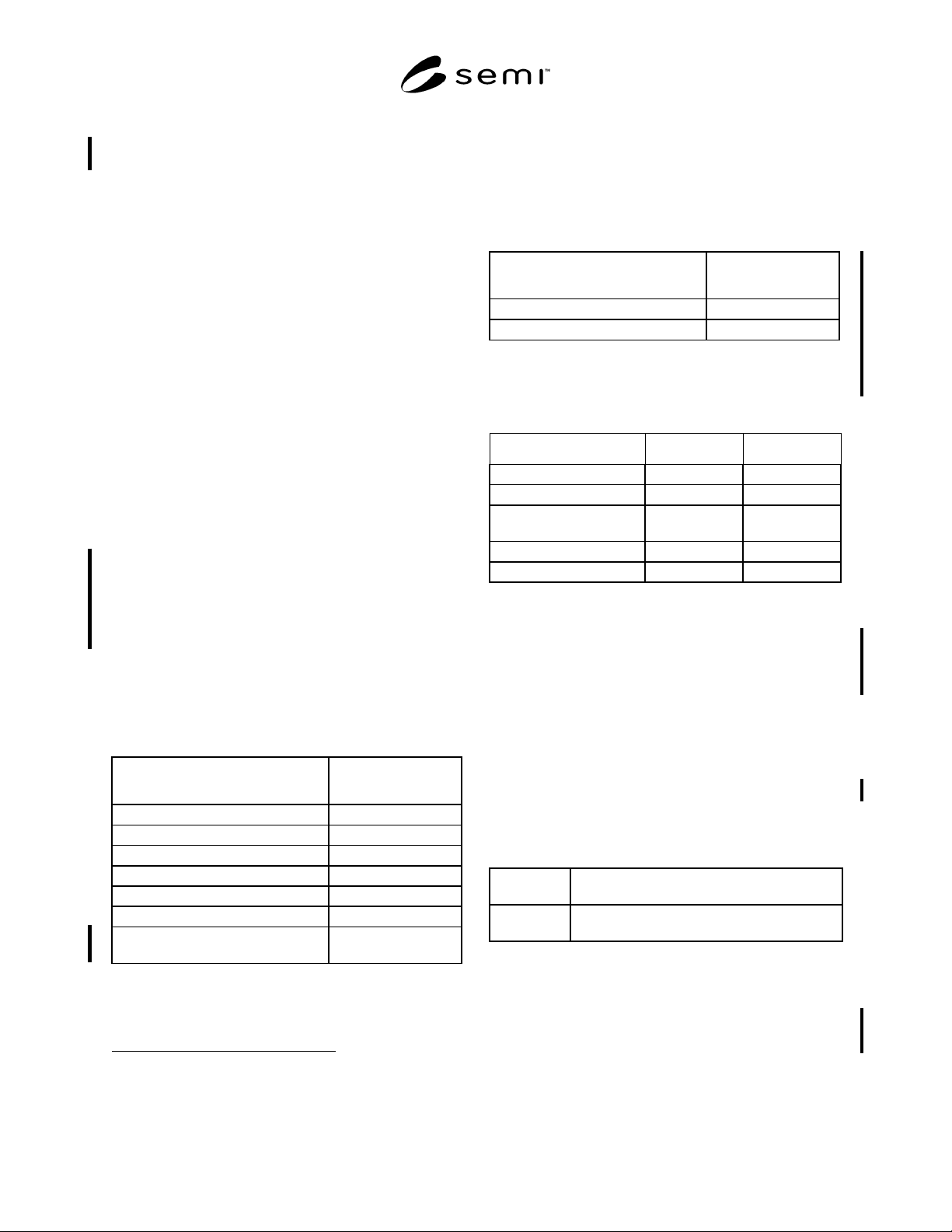
SPECIFICATION FOR BORON TRICHLORIDE (BCl
3
), 99.98% QUALITY
This specification was technically approved by the Global Gases Committee and is the direct responsibility of
the North American Gases Committee. Current edition approved by the North American Regional Standards
Committee on August 27, 2001. Initially available at www.semi.org September 2001; to be published
November 2001. Originally published in 1995.
1 Purpose
1.1 To define the specification and analytical methods
and validate the specifications for BCl
3
.
2 Scope
2.1 This specification relates to a geometry of 0.5 µ or
less (0.35 to 0.5 range) and describes analytical
techniques using gas phase analysis.
3 Description
3.1 Boron trichloride is a colorless toxic and corrosive
gas at room temperature and atmospheric pressure
which fumes in the presence of moist air. It has a
choking odor.
4 Referenced Standards
4.1 ISO Standards
1
ISO 6145-1 — Preparation of calibration gas mixtures –
Dynamic volumetric methods – Part 1: Methods of
calibration
NOTE 1: Unless otherwise indicated, all documents cited
shall be the latest published versions.
5 Specifications
Quality: 99.98% vapor phase
Impurities
Maximum Acceptable
Level (ppm)*
Nitrogen (N
2
)5
Carbon Dioxide (CO
2
)2
Chlorine (Cl
2
)10
Hydrogen Chloride (HCl) 100
Phosgene (COCl
2
)1
Silicon Tetrachloride (SiCl
4
)2
* TOTAL LISTED IMPURITIES
(excluding metals)
120
1 International Organization for Standardization, ISO Central
Secretariat, 1, rue de Varembé, Case postale 56, CH-1211 Geneva 20,
Switzerland. Telephone: 41.22.749.01.11; Fax: 41.22.733.34.30
Website: www.iso.ch
Impurities
Maximum Acceptable
Level (ppm)*
Iron (Fe) 0.5 wt.
Nickel (Ni) 0.5 wt.
* An analysis of significant figures has not been considered. The
number of significant figures will be based on analytical accuracy and
precision of the provided procedure.
6 Physical Constants (for information only)
Metric Units US Units
Molecular weight 117.17 117.17
Boiling point at atm 12.4°C 54.3°F
Density of gas at 20°C and
1 atm
5.326 kg/m
3
0.3325 lb/ft
3
Specific gravity 4.12 4.12
Density of liquid at –18°C 1372.8 kg/m
3
85.76 lb/ft
3
7 Analytical Procedures
NOTE 2: The boiling point of boron trichloride is 12.4°C. It
is recommended that, prior to the sampling operation, the
cylinder should be allowed to reach room temperature to
prevent the possibility of any suck-back.
7.1 Nitrogen — This procedure is for the determination
of nitrogen in boron trichloride using a gas
chromatograph fitted with a backflush valve and a
thermal conductivity detector.
7.1.1 Detection Limits — 0.5 ppm nitrogen.
7.1.2 Instrument Parameters
7.1.2.1 Columns:
Column 1: Porapak QS 60/80 mesh 2 m (6 ft) × 3.2 mm
(1/8") OD SS or equivalent.
Column 2: Molecular sieve 5A 60/80 mesh 2 m (6 ft) × 3.2
mm (1/8") OD SS or equivalent.
7.1.2.2 Carrier Gas Flow — Helium N6.0 Flow 25
mL/min
NOTE 3: The helium carrier gas should contain less than 10
ppb of the impurities it is desired to measure. This is best
achieved by using a commercial helium gas purifier.
7.1.2.3 Sample Volume — 2.5 mL.
SEMI C3.51-1101 © SEMI 1995, 2001 2
7.1.2.4 Temperatures:
Column Temperature 100°C
Detector Temperature 100°C
7.1.2.5 Bridge Current — 200 mA.
7.1.3 Calibration Standard — 1–10 ppm nitrogen in
helium.
7.1.3.1 Calibration — Construct a calibration curve in
the range of interest. Verify the standards employed
independently by established traceability to recognized
national or international standards.
7.1.4 Operating Procedure
7.1.4.1 Inject the calibration standard into the column
using a gas sampling valve. Adjust the backflush valve
operation sequence to present the nitrogen. Record the
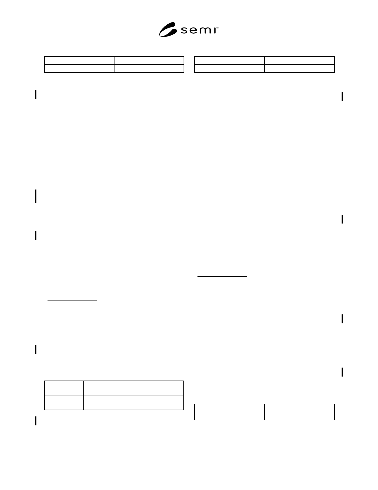
retention time and peak area. A sample chromatogram
is shown in Figure 1.
NOTE 4: Introduce the calibration standard as many times as
necessary to achieve the desired precision.
7.1.4.2 Inject the sample to be tested in the same
manner as the calibration standard. Record the retention
time and peak areas (see Note 2).
7.1.4.3 Repeat Section 7.1.4.1.
7.1.4.4 Compare the average peak areas of the nitrogen
in the calibration standard to that of the boron
trichloride sample being tested. Calculate the
concentration of nitrogen using the formula below. The
results may not exceed the specification in Section 5 of
this standard.
Sample Pea
k
Are
a
Standard Peak Are
a
×
Concentratio
n
of Standard
=
Concentratio
n
of Sample
7.2 Carbon Dioxide — This procedure is for the
determination of carbon dioxide in boron trichloride
using a gas chromatograph fitted with a backflush and a
thermal conductivity detector.
7.2.1
Detection Limits — 0.5 ppm carbon dioxide.
7.2.2 Instrument Parameters
7.2.2.1 Columns:
Column 1 Porapak QS 60/80 mesh 3m (10 ft.) by 3.2
mm (1/8") OD SS or equivalent
Column 2 Porapak QS 60/80 mesh 2.5 m (8 ft.) by 3.2
mm (1/8") OD SS or equivalent
7.2.2.2 Carrier Gas Flow — Helium N6.0 flow 25
mL/mm (See Note 3.)
7.2.3
Sample Volume — 2.5 mL.
7.2.4
Temperatures:
Column Temperature 60°C
Detector Temperature 110°C
7.2.5 Bridge Current — 200 mA.
7.2.6 Calibration Standard — 1–5 ppm carbon dioxide
in helium.
7.2.6.1
Calibration — Construct a calibration curve in
the range of interest. Verify the standards employed
independently by established traceability to recognized
national or international standards.
7.2.7
Operating Procedure
7.2.7.1 Inject the calibration standard into the column
using a gas sampling valve. Adjust the backflush valve
operation sequence to present the carbon dioxide peak.
Record the retention time and peak area. A sample
chromatogram is shown in Figure 2 (see Note 4).
7.2.7.2
Inject the sample to be tested in the same
manner as the calibration standard (see Note 2). Record
the retention time and peak areas.
7.2.7.3
Repeat Section 7.2.7.1.
7.2.7.4 Compare the average peak areas of the carbon
dioxide in the calibration standard to that in the boron
trichloride sample being tested. Calculate the
concentration of carbon dioxide using the formula
below.
Sample Peak Are
a
Standard Peak Are
a
×
Concentratio
n
of Standard
=
Concentratio
n
of Sample
7.3 Chlorine — This procedure is for the analysis of
chlorine in boron trichloride using a gas chromatograph
with a thermal conductivity detector.
7.3.1
Detection Limits — 5 ppm chlorine.
7.3.2 Instrument Parameters
7.3.2.1 Column 60 m (200 ft.) 0.53 mm (1/32") ID
Dimethyl silicone megabore capillary column (Ristek
RTxi)
7.3.2.2
Carrier Gas — Helium: N6.0 25–30 mL/min
(See Note 3.)
7.3.2.3 Sample Volume — 2.0 mL.
7.3.2.4 Temperatures:
Column Temperature 100°C
Detector Temperature 110°C
7.3.2.5 Bridge Current — 200 mA.
SEMI C3.51-1101 © SEMI 1995, 20013
7.3.3 Calibration Standard — 5–10 ppm chlorine in
helium.
7.3.3.1 Calibration — Construct a calibration curve in
the range of interest. Verify the standards employed
independently by established traceability to recognized
national or international standards.
7.3.4
Operating Procedure
7.3.4.1 Inject the calibration standard into the column
using a gas sampling valve. Record the retention time
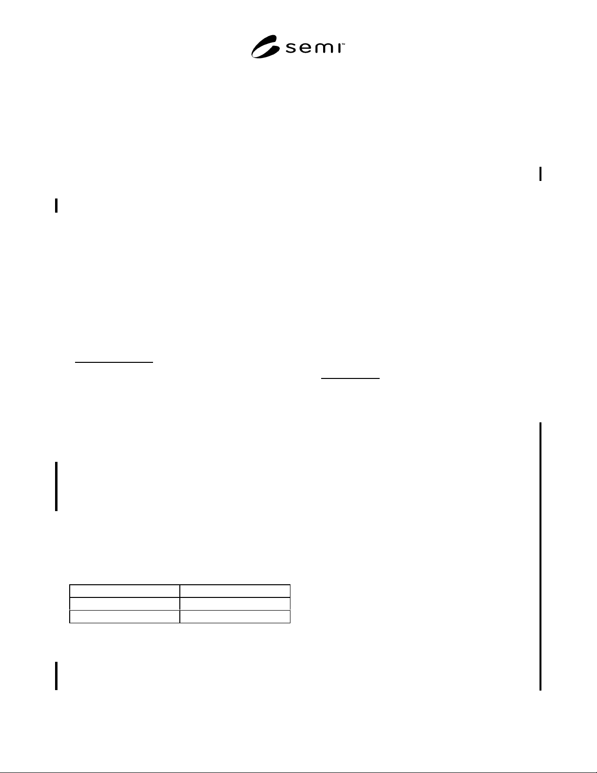
and peak area. A sample chromatogram is shown in
Figure 3 (see Note 4).
7.3.4.2
Inject the sample to be tested in the same
manner as the calibration standard. Record the retention
time and peak areas (see Note 2).
7.3.4.3
Repeat Section 7.3.4.1.
7.3.4.4 Compare the average peak areas of the chlorine
in the calibration standard with that obtained in the
boron trichloride sample being tested. Calculate the
concentration of chlorine using the formula below. The
results may not exceed the specification in Section 5 of
this standard.
Sample Pea
k
Are
a
Standard Peak Are
a
×
Concentratio
n
of Standard
=
Concentratio
n
of Sample
7.4 Hydrogen Chloride, Phosgene, and Silicon
Tetrachloride — This procedure is for the
determination of hydrogen chloride, phosgene, and
silicon tetrachloride using a Fourier transform infra red
(FTIR) analyzer.
7.4.1
Detection Limits
10 ppm hydrogen chloride
1 ppm phosgene
0.5 ppm silicon tetrachloride
7.4.2
Instrument Parameters
7.4.2.1 Cell Path Length — 16 cm × 16 mm ID K Br
windows
7.4.2.2 Wavenumbers:
Hydrogen Chloride 2970–2990 (cm
-1
)
Phosgene 855–865 (cm
-1
)
Silicon Tetrachloride 610–630 (cm
-1
)
7.4.2.3 The associated sampling system must be
equipped with inert gas purging and evacuation
capabilities.
7.4.3
Calibration Standards — Prepare calibration
standards for 10–100 ppm hydrogen chloride, 1–5 ppm
phosgene, and 0.5–5 ppm silicon tetrachloride in boron
trichloride.
NOTE 5: To ensure stability, the hydrogen chloride
calibration standard should be prepared dynamically using a
method defined in ISO 6145/part 1.1986. Phosgene and
silicon tetrachloride standards may be prepared by syringe
additions to liquid boron trichloride in the cooled sealed
container.
7.4.4 Operating Procedures
7.4.4.1 Evacuate and purge the sampling system
leading to the cell and purge the cell with dry nitrogen
for 30 minutes. Fill the cell with calibration standard.
Record the absorbance of hydrogen chloride, phosgene,
and silicon tetrachloride. A sample spectrum is shown
in Figures 4A, 4B, and 4C.
7.4.4.2
Fill the sample into the cell following the same
procedures used in Section 7.4.4.1 above. Record the
absorbance at the same wave number as the calibration
standard. Calculate the concentrations of hydrogen
chloride, phosgene, and silicon tetrachloride. The
results should not exceed the amount specified in
Section 3 of this specification.
Measure
d
Absorbance of
the Sample
Measured
Absorbance of
the Standard
×
Concentration
of Standard
=
Concentration
of Sample
NOTE 6: The following method should be adopted for
cleaning metallic parts used for sampling hydrogen chloride
gas:
a. Clean in a bath with methanol or isopropanol.
b. Ultrasonic clean in an appropriate solvent.
c. Rinse with isopropanol under Class 100 bench.
This cleaning method should be applied when a new cylinder
has to be connected and repeated after ten samplings, or if a
new cylinder has to be connected.
NOTE 7: Low-pressure plastic parts should be cleaned as
follows using 18 MΩcm water:
a. Fill sampling lines with the following solutions for 30
minutes: NH
4
OH 25%: H
2
O
2
35%: H
2
O = 1 to 1 to 5
parts by vol.
b. Wash sampling lines 5 times with water.
c. Fill sampling lines with the following solutions for 30
minutes: HCl 37%: H
2
O
2
35%; H
2
O = 1 to 1 to 5 parts
by vol.
d. Wash sampling lines a minimum of 5 times with water.
Terminate if the resistivity of the wash water from the
lines is more than 18 M
Ωcm.