semi合集-English.pdf - 第4936页
SEMI M9.7-0200 © SE MI 1995, 2000 2 _ (111) As _ (111) As _ (011) _ (001) (010) (110) (101) (001) (011) _ (110) _ _ (111) Ga (111) Ga _ (011) _ (101) (100) _ _ (011) KOH Etch Pit _ (010) Cross Sect ion of Etch Figure on …
SEMI M9.7-0200 © SEMI 1995, 20001
SEMI M9.7-0200
SPECIFICATION FOR ROUND 150 mm POLISHED
MONOCRYSTALLINE GALLIUM ARSENIDE WAFERS (NOTCHED)
This specification was technically approved by the Global Compound Semiconductor Committee and is the
direct responsibility of the North American Compound Semiconductor Committee. Current edition approved
by the North American Regional Standards Committee on December 15, 1999. Initially available at
www.semi.org January 2000; to be published February 2000. Originally published in 1995; previously
published in 1996.
NOTE: This document was rewritten in its entirety in
February 2000.
1 Purpose
1.1 This specification defines properties of 150 mm
monocrystalline GaAs substrates, in agreement with
presently established industry practice. It uniquely
defines those mechanical parameters that do not need,
for technical reasons, a choice of different values.
2 Scope
2.1 The parameters defined include the values and
tolerances of wafer diameter, thickness and surface
orientation. The position and depth of the notch and
laser marking are also specified.
2.2 The complete specification of this product includes
the requirements of SEMI M9, excluding those that are
not relevant to this specification (e.g., flat positions).
2.3 This standard does not purport to address safety
issues, if any, associated with its use. It is the
responsibility of the users of this standard to establish
appropriate safety and health practices and determine
the applicability of regulatory limitations prior to use.
3 Referenced Standards
3.1 SEMI Standards
SEMI M12 — Specification for Serial Alphanumeric
Marking of the Front Surface of Wafers
4 Physical Requirements
Table 1 Physical Requirements
Property Specification Tolerance Unit Reference
WAFER
Diameter 150.0
± 0.5
mm
Thickness, center point 675
± 25
µm
Surface orientation A (100) 0.5 max. degrees Figure 2
Surface orientation B
Tilt 2 off (100) towards (110)
± 0.5
degrees Figure 3
Orthogonal misorientation 0
± 5 max.
degrees Figure 4
NOTCH
Orientation [010]
± 2
degrees Figure 1
Depth 1.0 + 0.25, -0.0 mm Figure 5
Opening angle 90 + 5, -1 degrees Figure 5
LASER MARKING
Surface front side
Position adjacent to notch Figure 6
Mandatory content check characters SEMI M12
SEMI M9.7-0200 © SEMI 1995, 2000 2
_
(111)
As
_
(111)
As
_
(011)
_
(001)
(010)
(110)
(101)
(001)
(011)
_
(110)
_ _
(111)
Ga
(111)
Ga
_
(011)
_
(101)
(100)
_ _
(011)
KOH Etch Pit
_
(010)
Cross Section of Etch Figure
on Front Face of Wafer
Top View of LEC Crystal
Showing As and Ga Facet
A
s
Ga
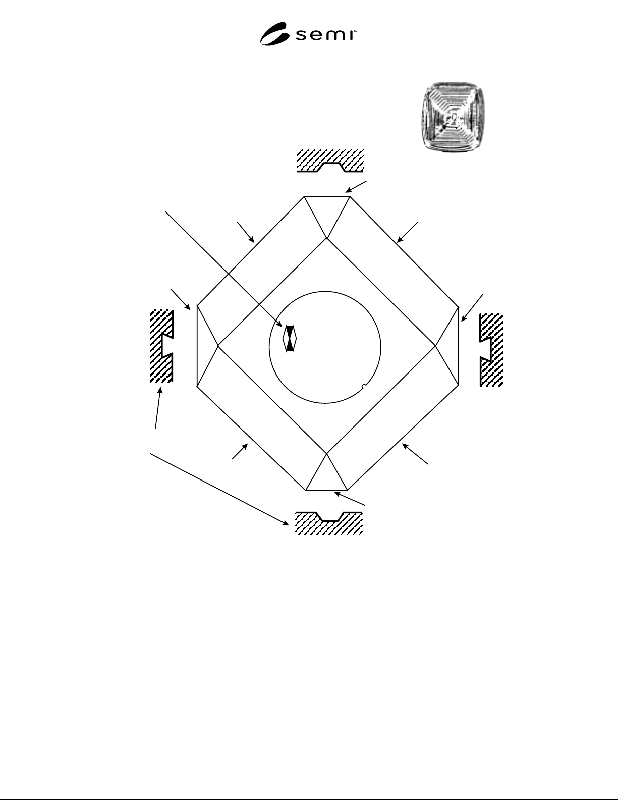
Figure 1
Diagram Shows a GaAs Wafer with Notch
SEMI M9.7-0200 © SEMI 1995, 20003
(111)Ga
Vector Normal
to Wafer Surface
(100)
Vector Normal
to (100) plane
_
(101)
_
(001)
_
(011)
(010)
_
_
(111)Ga
(110)
_
(111)
As
Tolerance
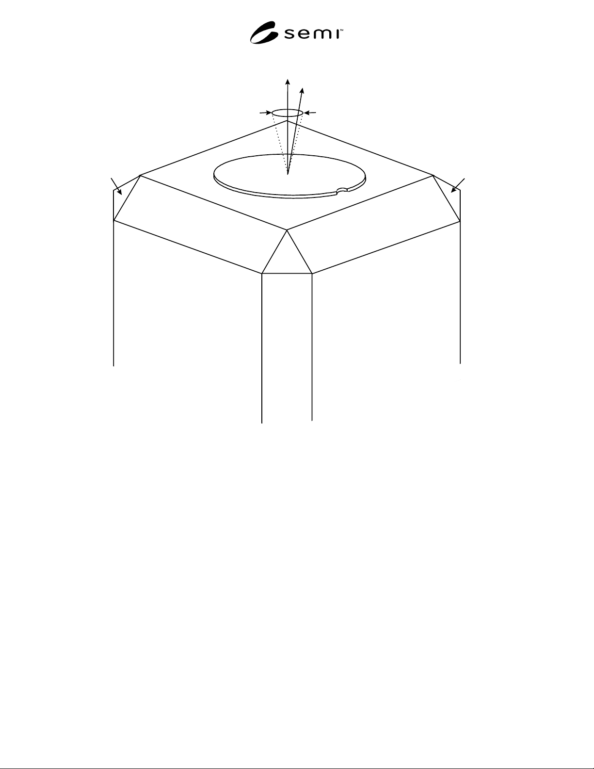
Figure 2
Notched GaAs Wafer Illustrating Surface Orientation A