semi合集-English.pdf - 第2437页
SEMI E87-0705 © SEMI 1999, 2005 6 7.3 Services 7.3.1 Services are functions or method s that may be provided by eith er the equipment or the host. A service message may be either a request message, which always re quires…

SEMI E87-0705 © SEMI 1999, 2005 5
7.2 State Model Methodology
7.2.1 A state model has three elements: definitions of each state and sub-state, a diagram of the states and the
transitions between states, and a state transition table. The diagram of the state model uses the Harel State Chart
notation. An overview of this notation is presented in an Appendix of SEMI E30. The definition of this notation is
presented in Science of Computer Programming 8, “Statecharts: A Visual Formalism for Complex Systems”, by D.
Harel, 1987
1
.
7.2.2 State Model Requirements
7.2.2.1 The state models included in this standard are a requirement for CMS compliance. A state model consists of
a state model diagram, state definitions, and a state transition table. All state transitions in this standard, unless
otherwise specified, shall correspond to collection events. More explicitly, there must be a unique collection event
for each state transition.
7.2.2.2 Equipment must maintain state models for each of the required state models as defined in this document.
Equipment shall maintain individual and unique state models for each logical entity instantiated or physical entity in
the equipment that has state models associated with it. The event identifier reported during a particular state
transition change for each of these state models shall be shared for all associated state models but unique for each
transition. For example, if the equipment has two load ports and the load port state model defines 10 transitions,
there must be exactly 10 event identifiers for each load port transfer state model but not 10 for each physical load
port. The information identifying the physical entity or logical entity undergoing the transition will be contained
within the associated event report.
7.2.2.3 A state model represents the host's view of the equipment, and does not necessarily describe the internal
equipment operation. All CMS state model transitions shall be mapped sequentially into the appropriate internal
equipment collection events that satisfy the requirements of those transitions. In certain implementations, the equip-
ment may enter a state and have already satisfied all of the conditions required by the CMS state model for transition
to another state. In this case, the equipment makes the required transition without any additional actions in this
situation.
7.2.2.4 Some equipment may need to include additional sub-states other than those in this standard. Additional sub-
states may be added, but shall not change the CMS defined state transitions. All expected transitions between CMS
states shall occur.
7.2.2.5 Transition tables are provided in conjunction with the state diagrams to explicitly describe the nature of each
state transition. A transition table contains columns for Transition number, Previous State, Trigger, New State,
Actions, and Comments. The “trigger” (column 3) for the transition occurs while in the “previous” state. The
“actions” (column 5) includes a combination of:
Actions taken upon exit of the previous state,
Actions taken upon entry of the new state, and
Actions taken which are most closely associated with the transition.
7.2.2.6 When a state model is defined with multiple AND sub-states, the equipment may report all state entry
events with only one collection event. When conditional paths are defined in the state model, it is not necessary to
report any state transition(s) until a terminal state is reached at which time each transition used to reach that state is
reported.
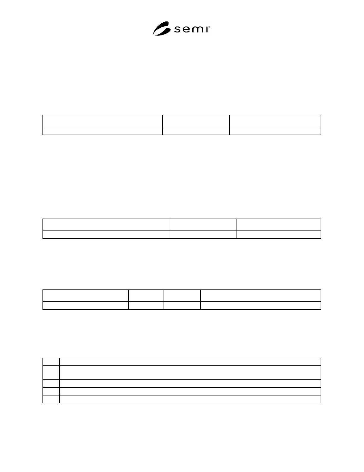
Table 2 State Transition Table
Num Previous State Trigger New State Actions Comments
1 Elsevier Science, P. O. Box 945, New York, NY 10159-0945, http://www.elsevier.nl/homepage/browse.htt
SEMI E87-0705 © SEMI 1999, 2005 6
7.3 Services
7.3.1 Services are functions or methods that may be provided by either the equipment or the host. A service
message may be either a request message, which always requires a response, or a notification message that does not
require a response.
7.3.2 Service Message Description
7.3.2.1 A service message description table defines the parameters used in a service, as shown in the following
table:
Table 3 Service Message Description Table
Service Name Type Description
#1
Type can be either “N” = Notification or “R” = Request & Response.
7.3.2.2 Notification type messages are initiated by the service provider (e.g., the equipment) and the provider does
not expect to get a response from the service user. Request messages are initiated by a service user (e.g., the host).
Request messages ask for data or an activity from the provider. Request messages expect a specific response
message (no presumption on the message content).
7.3.3 Service Message Parameter Definition
7.3.3.1 A service parameter dictionary table defines the description, range, and type for parameters used by
services, as shown in the following table:
Table 4 Service Message Parameter Definition Table
Parameter Name Form Description
#1
A row is provided in the table for each parameter used on a service.
7.3.4 Service Message Definition
7.3.4.1 A service message description table defines the parameters used in a service message. It also describes each
message and its cause/effect to the equipment. The columns labeled Req/Ind and Rsp/Conf link the parameters to the
direction of the message.
Service Parameter Req/Ind Resp/Conf Description
7.3.4.2 The columns labeled Req/Ind and Rsp/Conf link the parameters to the direction of the message. The
message sent by the initiator is called the “Request”. The receiver terms this message the “Indication”. The receiver
may then send a “Response”, which the original sender terms the “Confirmation”.
7.3.4.3 The following codes appear in the Req/Ind and Rsp/Conf columns and are used in the definition of the
parameters (e.g., how each parameter is used in each direction):
“M” Mandatory Parameter – must be given a valid value.
“C” Conditional Parameter – may be defined in some circumstances and undefined in others. Whether a value is given may
be completely optional or may depend on the values of other parameters.
“U” User-Defined Parameter.
“-” The parameter is not used.
“=” (for response only) Indicates that the value of this parameter in the response must match that in the primary (if defined).
SEMI E87-0705 © SEMI 1999, 2005 7
7.4 Alarm Requirements Definition
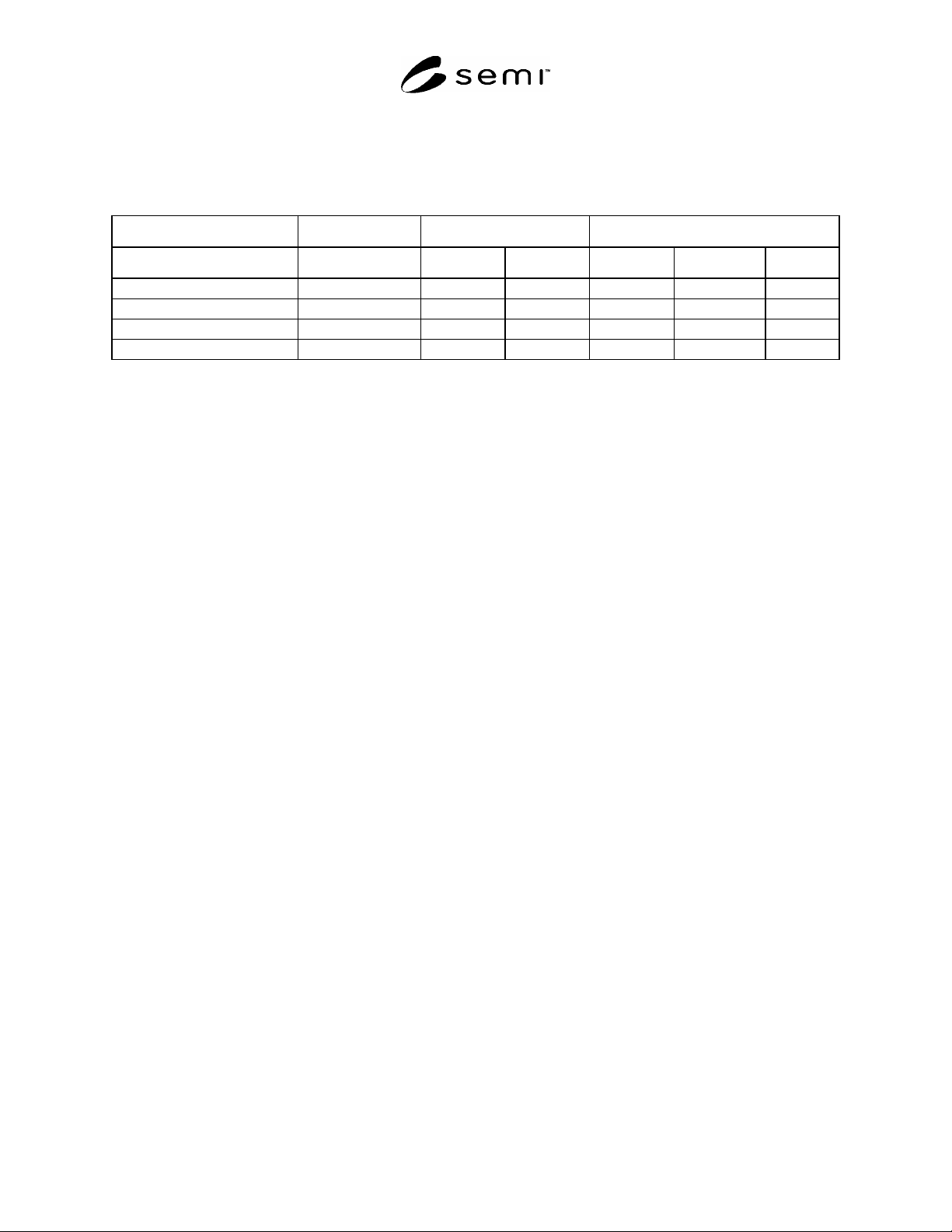
7.4.1 An alarm requirements definition table defines the specific set of alarms required by CMS. The table is
divided up by equipment configuration, and then by alarm. The danger and affected columns are marked with “X”
characters to show each alarm and its possible impact to operators, equipment, and material. The table format is
shown in the following example:
Equipment Danger Affected
Configuration Alarm Text Potential Imminent Operator Equipment Material
Configuration 1 Alarm 1 X X X X
Alarm 2 X X
Configuration 2 Alarm 3 X X X
Alarm 4 X X X
8 Overview
8.1 CMS defines the behavior, data, and services required for equipment supporting automated carrier transfer. This
document provides a standard interface for host/equipment communications regarding the transfer of carriers. The
standardized carrier transfer host interface includes not only transfers to and from the external load ports, but also
transfers to and from the internal buffer positions on internal buffer type equipment.
8.2 Single Connection Requirement
8.2.1 The expectation of the production equipment supplier is that this standard be implemented in conjunction with
the GEM interface to their production equipment and without the use of a separate communication connection.
9 Load Port
9.1 A load port (port) is used by the factory to load and unload carriers to and from production equipment. A load
port may be used as an input load port, an output load port, or as an input/output load port, depending upon
equipment type, configuration and/or factory practices. This classification may be fixed or it may be programmable
by the user. A load port is generally designed to handle one specific carrier type, such as substrate cassettes,
leadframe magazines, SMIF pods, or FOUPs.
9.2 Load Port Numbering
9.2.1 The load port number shall be assigned incrementally from the bottom left to bottom right, then top left to top
right when facing the front of the equipment. The load port numbering requirement is to provide a common
reference base to external entities, such as humans.
9.3 Carrier Slot Numbering
9.3.1 The slot numbers for a carrier shall be assigned incrementally from the bottom, starting with “1.”
9.4 Load Port Resource Sharing
9.4.1 A model of a load port must account for any mechanical assemblies that are either active during carrier
transfer or are capable of interacting with the transfer. The load port is responsible for such mechanisms when the
load port is in the TRANSFER READY state. If these mechanisms are shared with other load ports, then the sharing
must be coordinated.
9.5 Load Port Transfer State Model
9.5.1 The purpose of the Load Port Transfer State Model is to define the host view of a carrier transfer, which
includes the host interactions with the equipment necessary to transfer carriers to and from equipment load ports.
Each load port on the equipment shall maintain an independent instance of this state model.
9.5.2 Load Port Transfer State Model Diagram
9.5.2.1 Figure 1 is the diagram for the Load Port Transfer State Model.