semi合集-English.pdf - 第5994页
SEMI P43-0304 © SEMI 2004 3 NOTE 4: It is possible that some features ar e only included in part, see clipped feature. 5.12 region of inter est (ROI) — circumscribed section of a pattern t h at contain s (parts of) the f…
SEMI P43-0304 © SEMI 2004 2
SEMI Compilation of Terms
4.2 ISO Standards
2
International Vocabulary of Basic and General Terms
in Metrology
4.3 Other Standards
International Technology Roadmap for Semiconductors
(ITRS)
3
NOTICE: Unless otherwise indicated, all documents
cited shall be the latest published versions.
5 Interpretation of Related General
Terminology
NOTE 1: This paragraph includes general terms, as a basis
for the specific mask related terminology, which is the main
subject of this document.
5.1 feature — as defined in SEMI P35.
5.2 proximity range — distance over which a feature
influences another significantly (criterion to be stated).
This term applies to mask fabrication, mask metrology
and/or printed wafer image, defining 3 types of
proximity range (for example mask fabrication
proximity range). It is mandatory to state which of the
3 types is referred to.
NOTE 2: Within this document proximity range will refer by
DEFAULT to the first type mentioned.
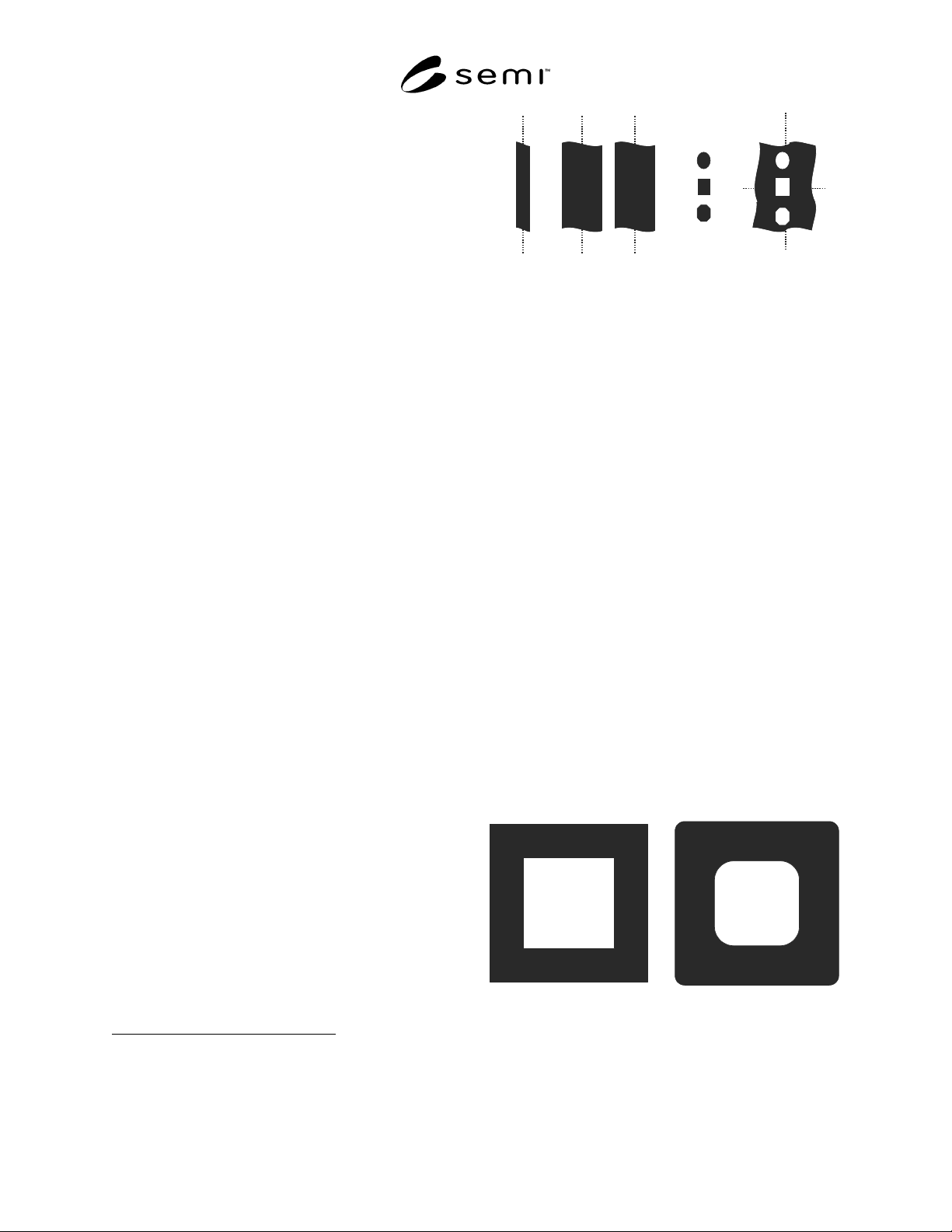
5.3 line — a clear field, dark feature of quasi-infinite
length (>> proximity range) determined by its width. A
line is an example of a 1D feature (see Figure 1).
5.4 space — in analogy to line, but a clear feature in a
dark field (see Figure 1).
5.5 contact — a clear feature in a dark field with
length:width ratio ranging from 0.5 (1 is default) to 2
maximum (see Figure 1). The width of such feature
may be measured as if it were a 1D feature, but for
enhanced relevance it requires 2D assessment such as
an area measurement. A large contact can be called a
window.
5.6 dot — in analogy to contact, but a dark feature in a
clear field (see Figure 1). A large dot can be called a
pad.
5.7 isolated feature — feature that has no neighbors
that are within a distance smaller than the proximity
range to any edge of the feature.
2 International Organization for Standardization 1, rue de Varembé
Case Postale 56 CH-1211 Genève 20 Switzerland
3 International Technology Roadmap for Semiconductors, organized
by International SEMATECH, 2706 Montopolis Drive, Austin, Texas
78741, see itrs.org
line space dots contacts
Figure 1
Nomenclature for Feature Types (as Designed)
Default contact (dot) is square.
5.8 dense features — features that influence each other
(i.e., features that are not isolated). Clarification is
required to describe the proximity, either by detailing
the feature pitch and number of lines, for regular arrays
(pitch = design values of line width and space width
added), or by describing the surrounding area (see
Section 7). In absence of such clarification dense is
regarded by default as equal lines and spaces in a semi-
infinite array size, insofar that the feature width does
not exceed the proximity range.
5.9 nominal feature — feature as it is
intended. This
usually corresponds to the data used for mask making,
including any pre-compensation to overcome process
biases of the wafer process (e.g., subresolution features
such as hammerheads and serifs), but excluding any
pre-compensation that is purely done to deal with mask
process limitations (e.g., chrome etch bias). In the
simplest case it corresponds to the original design itself.
5.10 actual feature — feature as it is on the mask. In
practical cases this will include deviations in feature
widths, lengths, shape and position from the nominal
feature.
NOTE 3: A feature, whether actual or nominal, may contain
holes, as shown in Figure 2.
Figure 2
Example of Features Containing Holes
(left: nominal; right: actual)
5.11 pattern — subset of a layout containing one or
more features.
SEMI P43-0304 © SEMI 2004 3
NOTE 4: It is possible that some features are only included in
part, see clipped feature.
5.12 region of interest (ROI) — circumscribed section
of a pattern that contains (parts of) the features
considered for measurement.
NOTE 5: It is recommended to make the ROI as small as
possible without affecting the obtained result.
5.13 clipped (nominal/actual) feature — the part of the
(nominal/actual) feature lying within the region of
interest (Figure 7).
5.14 feature (or Pattern) alignment — positioning of
nominal and actual feature (or pattern) relative to each-
other (see Section 8.4).
6 Coordinate System
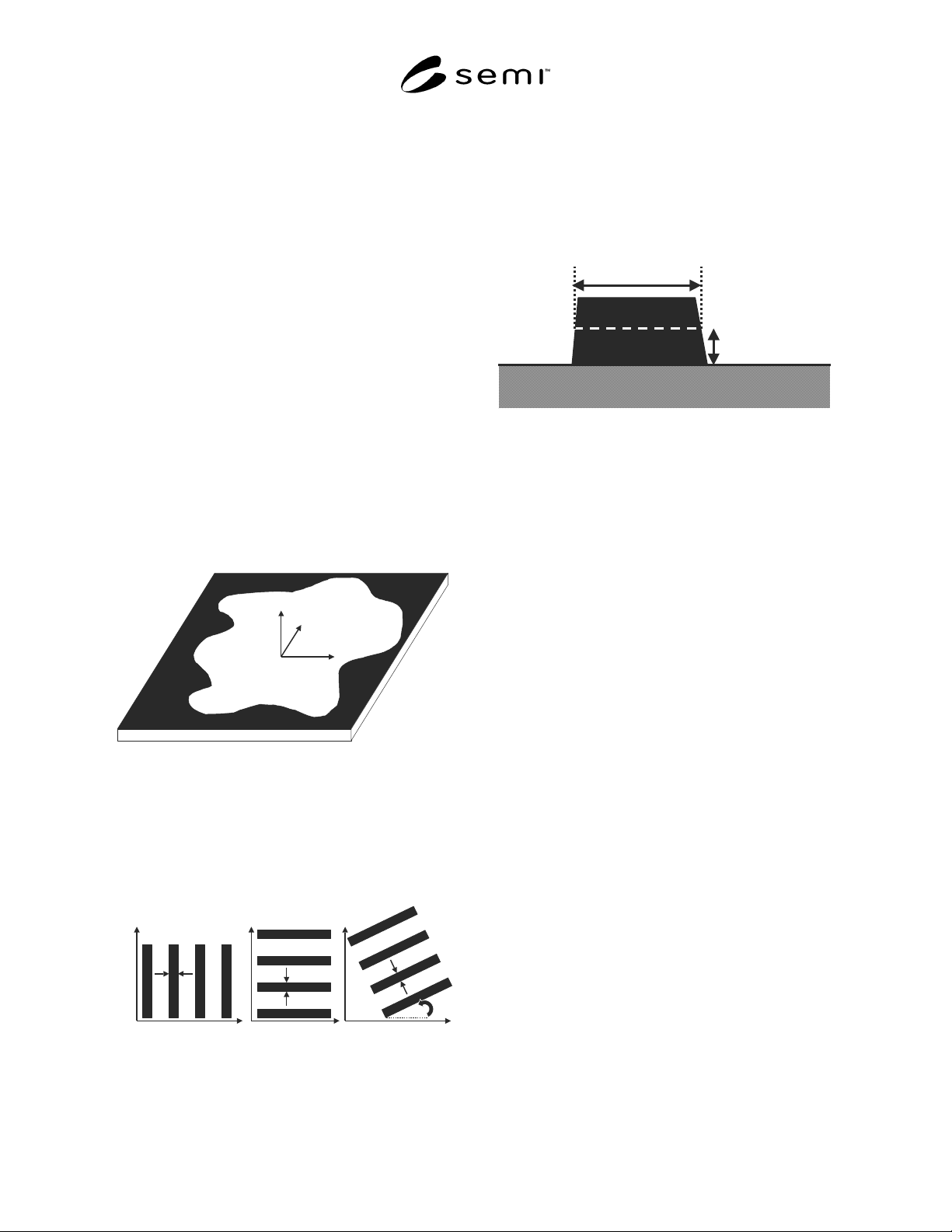
6.1 The coordinate system XYZ for this document is
defined in Figure 3. It is defined with patterned mask
side upwards and mask orientation as it was patterned.
XY determines the mask plane. Z is the direction
perpendicular to it. z = 0 at the absorber–substrate
interface and z < 0 to the substrate side. Absorber is for
example chrome or embedded material. (x,y) = (0,0) is
tool or application specific.
X
Y
Z
Figure 3
Mask Coordinate System
6.2 Features are called vertical when their length is
along Y. Feature width is then measured in X. This
corresponds to Figure 2 of SEMI P35. Horizontal
features have their length along X. Feature width is
then measured in Y. See Figure 4.
vertical
X
Y
horizontal
X
Y
other angle
X
Y
+
Figure 4
Orientation of Mask Features
7 1D Mask Qualification Terminology
7.1 feature width — width of a cross section of a mask
feature at a certain height defined by an appropriate
bounding box model as described in SEMI P35 (see
Figure 5). The bounding box model must be stated as
mandatory information, as well as the z height of the
measurement. DEFAULT is at z = 0.
width
height
Figure 5
Cross Section of a Mask Feature
7.2 measured feature width — width determined from
the measured signal obtained on the mask feature. For
example, the width may be determined at a certain level
of the measured signal. To be stated as mandatory
information:
• region of interest. For 1D features this corresponds
to the specified line segment (SEMI P35),
• measurement method used (SEM, optical
reflection, optical transmission, AFM, etc.),
• calibration and/or correlation used,
• precision (SEMI P24),
and as optional information:
• measurement tool (vendor, model or any tool
specific options), and
• measurement algorithm used.
NOTE 6: The bounding box could be infinitely short as in the
special situation of a measurement of a feature using a cross-
section.
7.3 feature width deviation (from target) — difference
between actual and nominal feature width.
7.4 measured feature width deviation (from target) —
difference between measured and nominal feature
width.
7.5 feature edge — position of the material boundary
of a mask feature at a certain height of the physical
cross section (see Figure 2 of SEMI P35), to be stated
as mandatory information. DEFAULT is
feature/substrate interface.

SEMI P43-0304 © SEMI 2004 4
7.6 measured feature edge — position determined
from the measured signal obtained on the mask feature
edge. For example position determined at a certain
level of the signal, as defined by the bounding box
model of SEMI P35. The same mandatory/optional
information must be stated as for measured feature
width.
7.7 critical dimension (abbreviated to CD) — a user
defined feature width of interest, mainly used for
further qualification. The critical dimension can be
plural. DEFAULT CD is one width and one pitch.
Mandatory information is the nominal feature width
and pitch.
NOTE 7: The ITRS mask table assumes multiple pitches.
7.8 feature width uniformity — the spread of the
distribution of the width of all mask features of a given
design size, selected as detailed hereafter. To be stated
as mandatory information:
• its targeted feature width,
• the criterion used (range, 3-sigma, maximum
deviation, etc.), where sigma stands for standard
deviation. Recommendation: before 3-sigma is
relevant, the distribution needs to be “normal” or
“near normal”, and the number of measurements
should be > 30,
• type and tone of features considered (line, contact,
space, etc. as defined in SEMI P19),
NOTE 8: Several types and/or tones of features could be
combined, but the recommendation is one tone and one
type, DEFAULT is lines for clearfield, spaces for
darkfield).
• all orientations considered (adopting a pre-
determined mask orientation, based on the
coordinate system in Section 6), for example
horizontal and vertical together, horizontal only,
vertical only, including other angles, horizontal-
and-vertical separately, etc. DEFAULT is
horizontal and vertical together,
• the pitch of the feature (or in general: a description
of the surrounding area, see further), e.g., equal
lines and spaces, isolated line, etc., or (if wished,
but not recommended) an interval of pitches, and
NOTE 9: In case of multiple pitches the defined feature
width uniformity would not be proximity free.
DEFAULT is one fixed pitch, to be mentioned. (The
ITRS mask table assumes multiple pitches.)
• The considered area of interest on the mask.
7.9 measured feature width uniformity — measured
value of feature width uniformity, stating as mandatory
information in addition to that of measured feature
width and feature width uniformity:
• the number of measurement points used,
• the measured area on the mask,
and as optional information:
• the spatial distribution of measurement locations,
e.g., by their coordinates. DEFAULT is spread
evenly over the measurement area.
7.10 (measured) CD uniformity — the special case of
feature width uniformity where the selected feature is
the critical dimension.
7.11 feature mean-to-target — the difference between
the mean width of features, selected as detailed, and
the targeted feature width, stating the same information
as for feature width uniformity. (DEFAULT: selecting
the same information and values as for feature width
uniformity.)
7.12 measured feature mean-to-target — the difference
between the mean of measured feature widths and the
targeted feature width, stating the same information as
for measured feature width uniformity. (DEFAULT:
selecting the same values as selected for measured
feature width uniformity.)
7.13 (measured) CD mean-to-target — the special case
of (measured) feature mean-to-target where the
selected feature is the critical dimension.
7.14 maximum feature width deviation from target —
maximum deviation of the width of a feature from its
target width in the total population of features
considered, stating the same information as in feature
width uniformity. (DEFAULT: selecting the same
information and values as used for feature width
uniformity.)
7.15 measured maximum feature width deviation from
target — maximum deviation of the measured width of
a feature from its target width in the population of
measurements, stating the same information as in
measured feature width uniformity. (DEFAULT:
selecting the same values as used for measured feature
width uniformity.)
NOTE 10: (Measured) maximum feature width deviation
from target combines (measured) feature width uniformity
and (measured) mean-to-target.
7.16 mean X-Y deviation — the difference between the
mean of considered feature widths in X and Y
directions (horizontal and vertical direction), stating the
same information as feature width uniformity.
(DEFAULT: selecting the same values as used for
feature width uniformity.)