semi合集-English.pdf - 第637页
SEMI E84-0305 © SEMI 1999, 2005 35 APPENDIX 1 APPLICATION NOTES NOTICE : The material in this appendix is an offici al part of SEMI E84 and was approved by full letter b allot procedures on July 21, 2002. The recommendat…
SEMI E84-0305 © SEMI 1999, 2005 34
Pin # Passive Side (connector
A) Signal Name
(See Figure 16)
Active Side (connector
B) Signal Name
(See Figure 16)
Symbol Direction Remarks
23 Power NC
#1
not applicable For wire based communication,
power is isolated.
24 Power COM Signal COM not applicable For wire base communication,
Power COM is routed to Signal
COM.
25 Signal COM Power COM not applicable For wire base communication,
Power COM is routed to Signal
COM.
#1
NC = Not Connected
#2
Reserved = The pin may be used to support the signal required for a type of any interface unit. It cannot be used for current or future
implementations of this specification.
7 Related Documents
7.1 SEMI Standards
SEMI E4 — SEMI Equipment Communications Standard 1 Message Transfer (SECS-I)
SEMI E5 — SEMI Equipment Communications Standard 2 Message Content (SECS-II)
SEMI E15 — Specification for Tool Load Port
SEMI E37 — High-Speed SECS Message Services (HSMS) Generic Services
SEMI E64 — Provisional Specification for 300 mm Cart to SEMI E15.1 Docking Interface Port
7.2
Japanese Industrial Standards Committees
2
JIS-X-5103 — The Interface between Data Circuit Terminating Equipment (DCE) and Data Terminal Equipment
(DTE) (37/9-Pin Interface)
NOTE 5: As listed or revised, all documents cited shall be the latest publications of adopted standards.
2 Japanese Industrial Standards, Available through the Japanese Standards Association, 1-24, Akasaka 4-Chome, Minato-ku, Tokyo 107-8440,
Japan. Telephone: 81.3.3583.8005; Fax: 81.3.3586.2014 Website: www.jsa.or.jp

SEMI E84-0305 © SEMI 1999, 2005 35
APPENDIX 1
APPLICATION NOTES
NOTICE: The material in this appendix is an official part of SEMI E84 and was approved by full letter ballot procedures on
July 21, 2002. The recommendations in this appendix are optional and are not required to conform to this standard.
Determination of the suitability of the material is solely the responsibility of the user.
A1-1 General Applications Notes
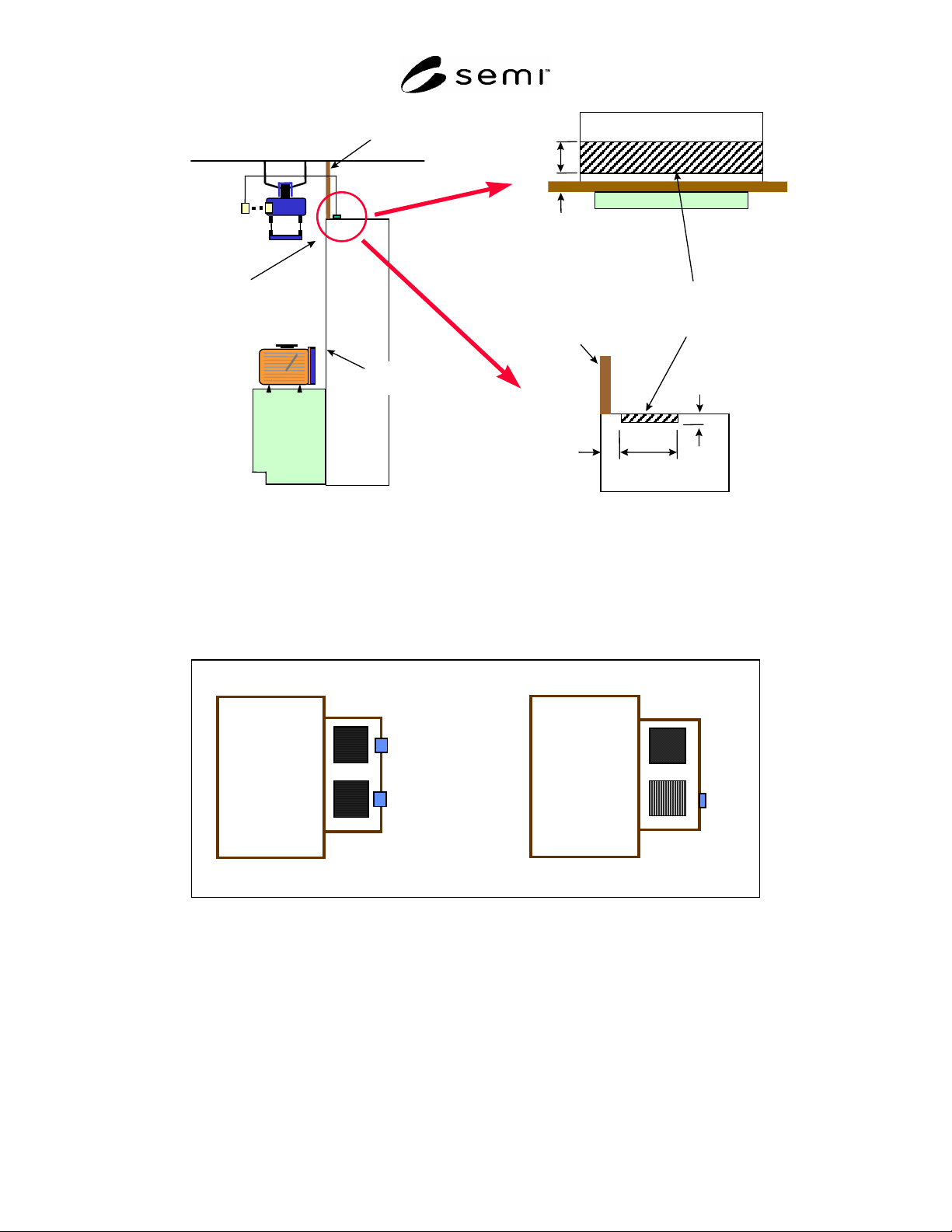
A1-1.1 If the connection to the equipment for overhead delivery is made using an electrical connector, Figure A1-1
defines a zone on the process or metrology equipment where the plug can be located. This zone is independent of
the exclusion zones for parallel I/O devices defined by SEMI E15.1. The zones defined in SEMI E15.1 are designed
to be used primarily for photo-coupled floor based delivery systems such as AGVs or RGVs, while the zone defined
here on the top of the passive equipment applies primarily to a plug for overhead communication. The plug should
be on the top or top edge of the equipment as shown and could be on either side of the bay/chase wall, depending on
the location of the wall. In some implementations, the wall may not exist.
A1-1.2
During the first few sequences of the SEMI E84 protocol before the carrier transfer begins if an error occurs
the active vehicle should send an error to the host which leads to an automatic recover without human intervention.
The active vehicle, on its own or in response to a host-initiated signal, should automatically recover any SEMI E84
error up to the BUSY ON state.
A1-1.3 No application of parallel I/O communication can provide perfect isolation due to Electro-magnetic
radiation into and between parallel conductors. Precautions should be taken, by all equipment suppliers, including
but not limited to insuring a minimum capacitance of signal lines to reduce susceptibility to noise introduced into the
equipment.
A1-1.4
There are two types of equipment, internal buffer equipment and fixed buffer equipment. Internal buffer
equipment is equipment that uses locations other than load ports within the equipment to store carriers. Fixed buffer
equipment is production equipment that has only fixed load ports and no internal buffer for carrier storage. Wafers
are loaded and unloaded directly from the carrier at the load port for processing.
A1-1.5
This standard specifies two different PI/O configurations, one PI/O per load port and one PI/O per two load
ports (Figure A1-2). Carrier transfer throughput and efficiency is higher if more than one carrier is transferred at the
same time. Carrier transfer time is also reduced if the intrabay AMHS equipment can deliver two or more carriers at
the same time from one parked position. Typically internal buffer equipment that allows hand-off of two carriers to
two load ports either simultaneously or continuously can best take advantage of these throughput improvements.
Thus, internal buffer equipment will require either one PI/O per load port (Figure A1-3, Concept A) or one PI/O per
two load ports (Figure A1-3, Concept B), depending on the AMHS delivery system. Fixed buffer equipment will
require one PI/O device per load port (Figure A1-4). Based on their production equipment and AMHS systems, end
users will specify the SEMI E84 concept (one PI/O per load port or one PI/O per two load ports) and location that
will be required on the manufacturing equipment.
A1-1.6
Figure 17 does not define a particular orientation of the PI/O interface sensor unit. Figure A1-5 shows how
to orient the PI/O device for AGV/RGV of the exclusion volume in the load port. Refer to SEMI E15.1 for
descriptions of D7, D8, H7, H8, and W8.
SEMI E84-0305 © SEMI 1999, 2005 36
Bay wall
(possible location)
SEMI
E15.1
Load port
ceiling
Female plug on
equipment -
interface point
Equipment
boundary
top view
100 mm
300 mm
zone where plug can be
located - top or top edge
of the equipment
side view
100 mm
300 mm
100 mm
Bay wall
(possible location)
Figure A1-1
Connection Plug Location for Overhead Delivery
Production Equipment Production Equipment
1 PI/O per 2 Load ports
1 PI/O per Load port
PI/O
PI/O
PI/O
Figure A1-2
Two Different PI/O Configurations