semi合集-English.pdf - 第4079页
SEMI F56-0600 © SEMI 2000 9 Table 2 Zero and Sp an Effects as a Functi on of Steady -State Power Supply Power Su pply Volta ge Change (% of reference) Change i n Zero of MFC (% FS) Span of MFC (% FS) Span - Actual Fl ow …
SEMI F56-0600 © SEMI 2000 8
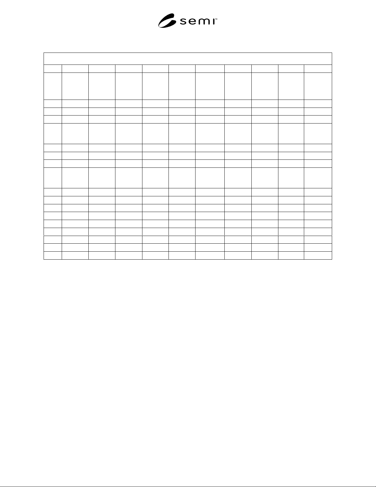
Table 1 Data Sheet
Data Sheet 1 Data from Steady State Power Supply Effects
Column A Column B Column C Column D Column E Column F Column G Column H Column L Column M
Data
Pnts
MFC
Setpoint
MFC
Indicated
Flow (V)
Flow
Standard
Output
(V)
Positive
Power
Supply
Level (V)
Negative
Power
Supply
Level (V)
Power
Supply
Current
Level (mA)
MFC
Indicated
Flow %FS
Flow
Standard
%FS
Positive
Power
Supply
Var. (%)
Negative
Power
Supply
Var. (%)
10 0 0 15-15 30 0 0 0 0
20 0 0 15-15 30 0 0
30 0 0 15-15 30 0 0
.
.
.
4 0 0.015 0 15.15 -15 30 0.3 0 1.0 0
5 0 0.010 0 15.15 -15 30 0.3 0
6 0 0.010 0 15.15 -15 30 0.3 0
.
.
.
7 0 0.015 0 14.85 -15 30 0.3 0 -1.0 0
8 0 0.010 0 14.85 -15 30 0.2 0
9 0 0.015 0 14.85 -15 30 0.3 0
.
10 0 0.010 0 15 -15.15 30 0.3 0 0 1.0
11 0 0.010 0 15 -15.15 30 0.3 0
12 0 0.010 0 15 -15.15 30 0.3 0
.
13 0 0.005 0 15 -14.85 30 0.1 0 0 -1.0
SEMI F56-0600 © SEMI 20009
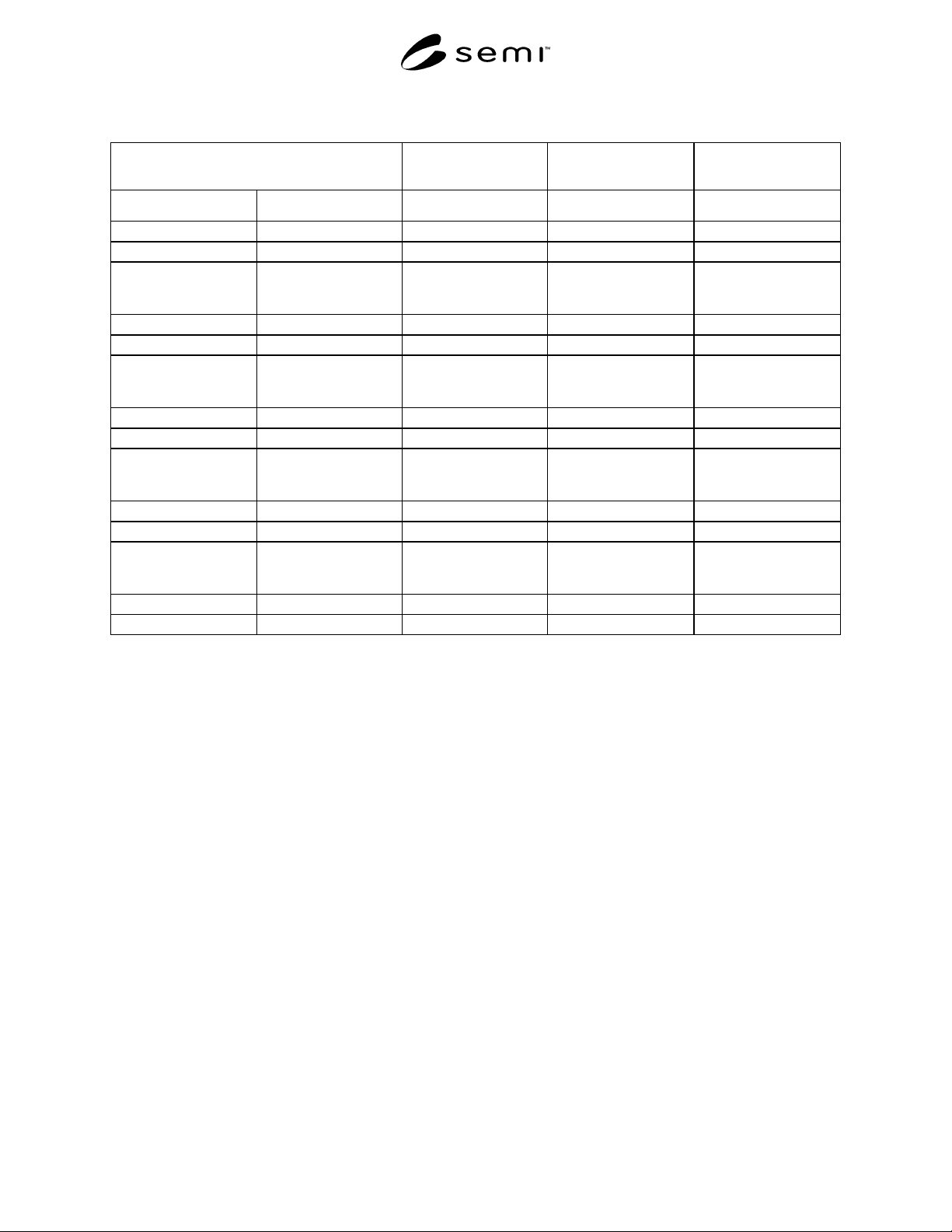
Table 2 Zero and Span Effects as a Function of Steady-State Power Supply
Power Supply Voltage Change
(% of reference)
Change in Zero
of MFC (%FS)
Span of MFC
(%FS)
Span - Actual Flow
(%FS)
Positive Negative
00000
-1 0 0.25 99.8 100.0
.
.
.
.
.
.
.
.
.
.
.
.
.
.
.
00000
-1 0
.
.
.
.
.
.
00
0+1
.
.
.
.
.
.
00
1-1
.
.
.
.
.
.
00
11
NOTICE: SEMI makes no warranties or representations as to the suitability of the test method set forth herein for
any particular application. The determination of the suitability of the test method is solely the responsibility of the
user. Users are cautioned to refer to manufacturer’s instructions, product labels, product data sheets, and other rele-
vant literature respecting any materials mentioned herein. These test methods are subject to change without notice.
The user’s attention is called to the possibility that compliance with this test method may require use of copyrighted
material or of an invention covered by patent rights. By publication of this test method, SEMI takes no position
respecting the validity of any patent rights or copyrights asserted in connection with any item mentioned in this test
method. Users of this test method are expressly advised that determination of any such patent rights or copyrights,
and the risk of infringement of such rights, are entirely their own responsibility.
Copyright by SEMI® (Semiconductor Equipment and Materials
International), 3081 Zanker Road, San Jose, CA 95134. Reproduction o
f
the contents in whole or in part is forbidden without express written
consent of SEMI.
SEMI F57-0301 © SEMI 2000, 20011
SEMI F57-0301
PROVISIONAL SPECIFICATION FOR POLYMER COMPONENTS USED
IN ULTRAPURE WATER AND LIQUID CHEMICAL DISTRIBUTION
SYSTEMS
This specification was technically approved by the Global Facilities Committee and is the direct
responsibility of the North American Facilities Committee. Current edition approved by the North American
Regional Standards Committee on October 18, 2000. Initially available on www.semi.org November 2000;
to be published March 2001. Originally published October 2000.
NOTE: This specification is considered provisional since it
lacks a complete set of requirements for particles in Table 2
as well as particle test methods for components as noted in
Table 1. At the time of publication, only a small database of
values existed for PFA valves. Test methodologies will be
generated for components and this document will be re-
balloted at a later date.
1 Purpose
1.1 This document specifies minimum performance
requirements for ultrahigh purity (UHP) polymer
components used throughout semiconductor ultrapure
water and liquid chemical distribution systems
including bulk supply, facility distribution, and process
equipment applications.
2 Scope
2.1 Polymer component purity and mechanical
specifications are included in this standard along with
references for qualification test methods. Certification,
traceability, and packaging requirements are also
included.
Purity Requirements:
• Particle Contribution
• Ionic Contamination
• Metallic Contamination
• Total Organic Carbon Contamination
• Surface Roughness
Mechanical Requirements:
• Temperature/Pressure Rating
• Chemical Resistance Rating
• Reliability
2.2 Polymer piping system compo nents consisting of
but not limited to the items shown in Table 1 are
designed to contain and supply the following types of
liquid chemicals:
• Acids, bases and oxidizers
• Aqueous salt solutions
• Ultrapure Water (UPW)
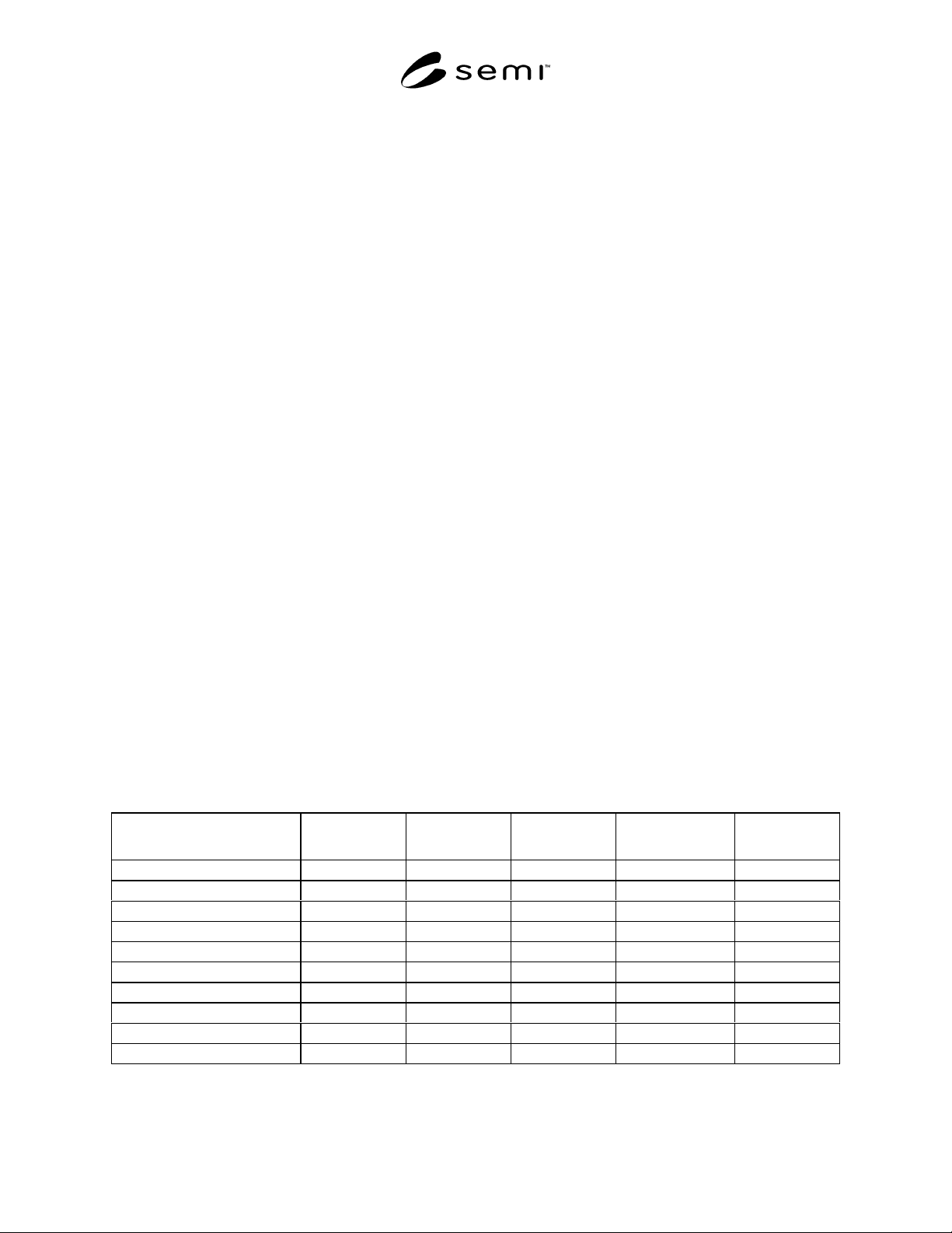
Table 1 Required Performance Specifications and Testing by Component Type
Test Particles Ionic
Contamination
Metallic
Contamination
Total Organic
Carbon
Surface
Roughness
Section 7.2 7.3 7.4 7.5 7.6
Table 2 3 4 5 6
Pipe/Tubing x x x x
Fittings x x x x
Valves (See NOTE 1.) x x x x
Filter Housings x x x x
Pressure Transducers x x x
Flow Meters x x x
Gauge Guards x x x
Regulators x x x
NOTE 1: A method for this requirement is being developed. At the time of publication, only a small database of values existed for PFA valves.
As the database encompasses more polymer materials, limits will be set for this parameter. Then, this document will be re-balloted.