semi合集-English.pdf - 第3904页
SEMI F30-0298 © SEMI 1998 2 10 Safet y Precaut ions 10.1 T he testin g area should have a d eq uate roo m venti latio n and atmo spher ic mo nitor s. 10.2 I nstrume nts sho uld b e exha ust e d to vent, a nd i f required…

SEMI F30-0298 © SEMI 19981
SEMI F30-0298
START-UP AND VERIFICATION OF PURIFIER PERFORMANCE
TESTING FOR TRACE GAS IMPURITIES AND PARTICLES AT AN
INSTALLATION SITE
1 Purpose
1.1 The purpose of this procedure is to verify the
performance of purifiers by employing analytical
instrumentation to measure gas impurities and particles
to customer specifications. If specific inlet challenge(s)
and/or inlet measurements are required, it should be
discussed beforehand with the customer. Inlet
impurities must be measured by part-per-million (PPM)
or part-per-billion (PPB) analytical equipment. This
procedure applies only to large scale bulk purifiers
rated at greater than 50 liters-per-minute (LPM)
flowrate.
2 Scope
2.1 Verify performance of large scale purifiers in
nitrogen, argon, helium, oxygen, and hydrogen service.
Verification tests are done at PPB or sub-PPB levels of
gaseous impurities and sub-micron sizes of particles
measured downstream of any installed filter modules.
Tests are done at maximum achievable flow of purifier,
and/or customer’s specified percentages of maximum
flow.
3 Limitations
3.1 PPB and sub-PPB gaseous impurity levels are
achievable using atmospheric presssure ionization mass
spectrometry (APIMS), which is the preferred method
of choice, and the reduction gas detector (RGD)-gas
chromatograph. APIMS is currently not available for
oxygen service. A partial list of non-APIMS measuring
equipment for use in oxygen service is in Appendix 1
for commonly measured impurities.
4 Referenced Documents
4.1 Approved procedures for operation of analytical
equipment.
4.2 Approved gas sampling and purifier procedures.
5 Terminology
None.
6 Summary of Method
6.1 The purifier is started, and the operation is
checked. Each purifier bed is regenerated, and
analytical tests are done. The analytical results
determine if the purified gas meets the customer
specifications.
7 Interferences
7.1 The following sources might contribute to
misleading or high analytical results. Some identified
sources are unpurged, dead-ended piping or isolation
valves, leaks in gas distribution system, insufficient
purge flow, and insufficient system clean-up time.
8 Apparatus
8.1 Face seal fitting(s) with metal gaskets and stainless
steel tubing for sampling.
8.2 Dynamic dilution system for diluting calibration
standards to PPB and sub-PPB levels for calibration of
analytical equipment.
8.3 APIMS — The sample gas, nitrogen, is introduced
into an APIMS where a small amount of it is ionized.
By collision with ionized nitrogen, impurity molecules
are ionized with high efficiency. The mass analyzer,
which can be a quadrupole, time-of-flight (TOF), or
even a magnetic sector, separates and focusses the ions
by their mass-to-charge ratio. An electron multiplier
detects and counts each ion fragment and amount.
8.4 Reduction Gas Detector-Gas Chromatograph
(RGD-GC) — The reduction gas detector is a heated
mercuric oxide bed that reacts with reducing gases,
such as hydrogen and carbon monoxide. The mercury
evolved is detected and displayed as a peak. The GC
employs a heated molecular sieve column to separate
the H
2
and CO.
8.5 Ultratrace Analytical Instrumentation Required
other than APIMS — Ultratrace instrumentation is
defined as having sufficient sensitivity to measure all
impurities of interest at the specified level of the
customer at the PPB or sub-PPB.
8.6 Particle counter.
8.7 Data collection and reduction system.
9 Reagents and Materials
9.1 Certified calibration standards.
SEMI F30-0298 © SEMI 1998 2
10 Safety Precautions
10.1 The testing area should have adequate room
ventilation and atmospheric monitors.
10.2 Instruments should be exhausted to vent, and if
required in Class 1 environments, should be case-
purged or in an approved enclosure.
10.3 Testing personnel should be aware of customer
alarm and evacuation procedures.
10.4 Designated customer contact required during
testing.
11 Sampling
11.1 Test each purifier bed independently to verify
performance to customer specifications. Refer to gas
supplier’s certificate of conformance for inlet impurity
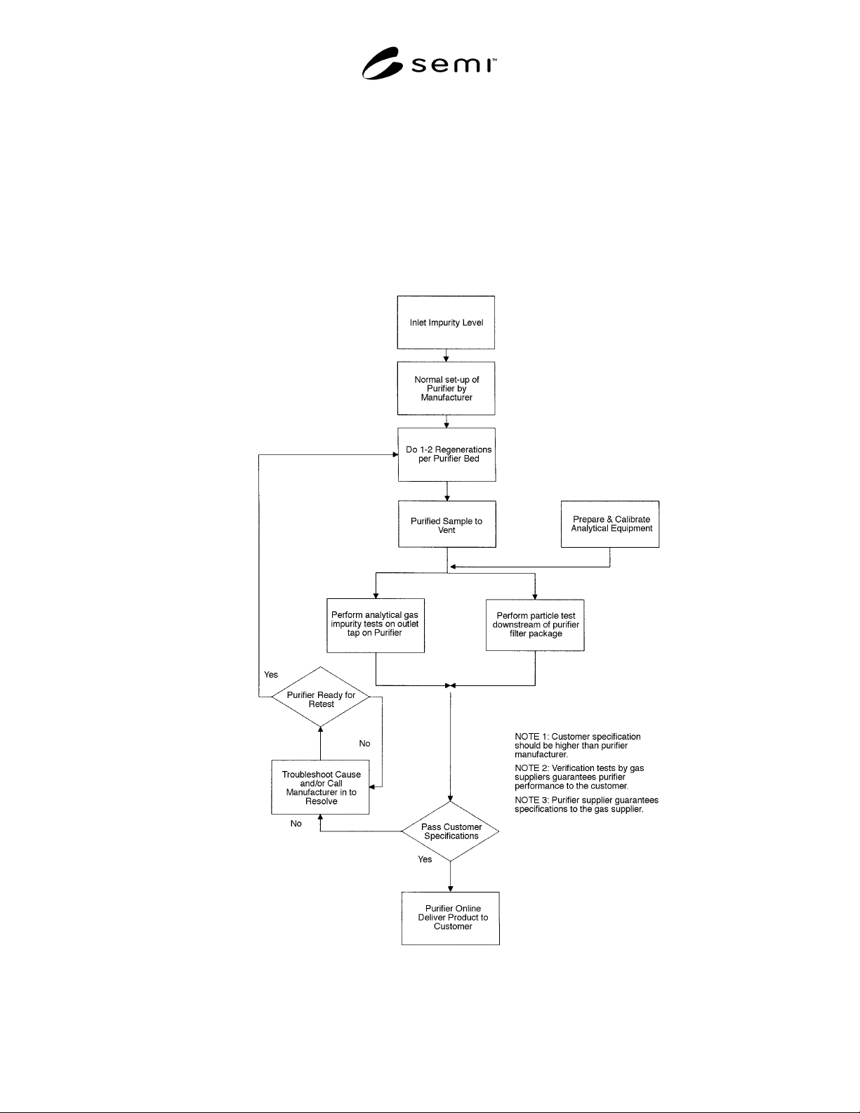
levels. Refer to Figure 1 for overall test sequence.
Figure 1
Overall Test Sequence

SEMI F30-0298 © SEMI 19983
12 Preparation of Apparatus
12.1 Sampling System — Use appropriate clean tubing
and fittings, or clean before use. Purge system prior to
sampling.
12.2 Dynamic Dilution System — Use certified
standards and dilute using equation (1) to calculate final
concentration (C
F
). For moisture, certified moisture
permeation devices can be used.
(1) C
c
× D.F. = C
F
C
c
= PPM - or PPB - certified cylinder standard concentration.
C
F
= final concentration.
D.F. = dilution factor which is calculated by taking the
flow (in liters) of the certified standard and dividing
by total flow (in liters). Dilution factors can be
multiplied in series, if diluting more than once.
Example 1: What is the final concentration for
dynamically diluting 10 ml of a 100 PPB impurity into
1 liter?
100 PPB × [0.010 liter/1.010 liter] = 0.99 PPB
12.2.1 Calibration should be done in the region
specified by the purifier manufacturer. For example, if
the purifier has an outlet impurity guarantee of 1 PPB
of each impurity, then the test equipment should be
calibrated with levels at approximately 1 PPB, not at 30
PPB and extrapolated down. Also, multipoint
calibration data is preferred.
12.3 APIMS, RGD-GC, ultratrace analytical
instrumentation. Particle counter.
12.3.1 Start-up and purge the instrumentation. Perform
calibration. Determine if calibration is satisfactory.
Proceed to sampling section.
12.4 Data Collection System — Check for proper
signal inputs, range inputs, and sampling intervals.
12.5 Data Reduction System — Prepare data as print-
outs and/or graphs. Include statistical analysis as
required. Generate final report.
13 Calibration and Standardization
13.1 See Section 12, Preparation of Apparatus.
14 Procedure
14.1 Trace Gas Impurity Measurement
14.1.1 Connect sample source to analytical equipment.
14.1.2 Start data collection.
14.1.3 Stop sampling. Review preliminary data. If it is
within customer specification, disconnect sample
source. If it does not meet specifications, investigate
cause or refer to manufacturer literature to resolve.
Once condition is corrected, repeat tests.
14.1.4 Repeat procedure for next bed or sampling
point. If instrumentation is relocated, calibration check
is required.
14.2 Particle Counting
14.2.1 Select sample location. Ideal location is a
permanently installed pitot probe.
14.2.2 Select where the particle tests will be done on
the pipe.
14.2.3 Use Reynold’s equation to determine the
required gas rate for turbulent flow to the particle
counter. Use this value or higher for sampling purposes.
Reynold’s number greater than 2100 are suggested for
turbulent flow.
14.2.4 Reduce incoming sample pressure to the
particle counter by following manufacturer’s
recommendation or by best practice.
14.2.5 Test particles with turbulent flow through
pipeline, if possible. However, do not exceed the
manufacturer’s maximum rated flow for the purifier.
14.2.6 Start data collection.
14.2.7 Stop sampling. Review preliminary data. If it is
within customer specification, disconnect sample
source. If it does not meet specifications, investigate
cause or refer to manufacturer’s literature to resolve.
Once condition is corrected, repeat tests.
14.2.8 Repeat procedure for next bed or sampling
point.
15 Calculations or Interpretation of Results
15.1 Results are interpreted by trending analysis,
averaging, or steady-state analysis.
16 Reporting Results
16.1 Sample location.
16.2 Operator identification.
16.3 Test parameters and conditions (pressures,
flowrates, temperatures, etc.).
16.4 Test date and duration.
16.5 Description of instrumentation.
16.6 Calibration information for analyzer(s).
16.7 Report test results by data table and/or graphs.
16.8 Comments on testing.
16.9 Conclusion.