semi合集-English.pdf - 第6436页
SEMI G75.11-06 98 © SEMI 1998 2 Figure 2 Electrodes Formed on the Leadframe Tape Figure 3 Electrode Connection
SEMI G75.11-0698 © SEMI 19981
SEMI G75.11-0698
TEST METHOD FOR MEASUREMENT OF THE DIELECTRIC
CONSTANT AND DISSIPATION FACTOR OF THE LEADFRAME TAPE
1 Purpose
1.1 Capacitance is measured for tape specimens and
air with similar electrode setups. Dielectric constant and
dissipation factor of the tapes are calculated from the
results.
2 Referenced Documents
NOTE: As listed or revised, all documents cited shall be the
latest publications of adopted standards.
2.1 JIS Specification
1
JIS K 6911 — Testing Methods for Thermosetting
Plastics
3 Equipment
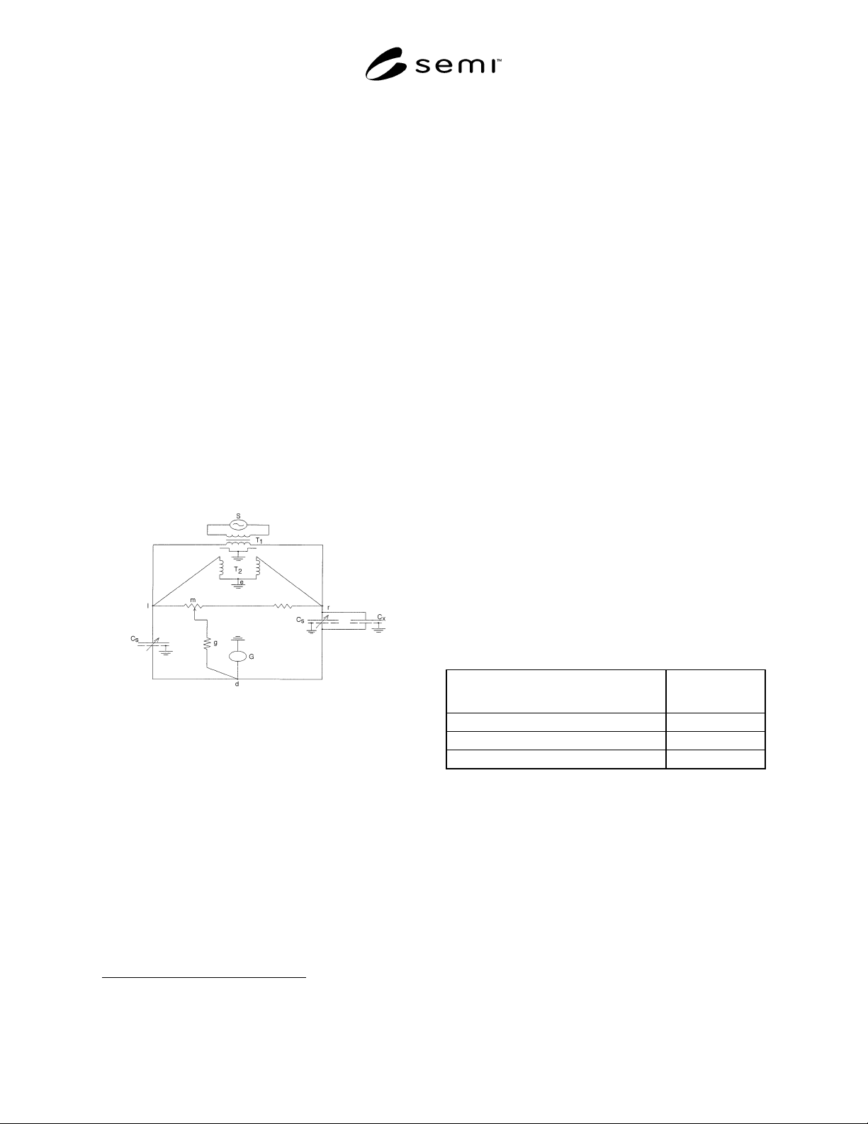
3.1 Measurement Circuit — See JIS K 6911 5.14.2 (1)
(b)-(d) and Figure 1.
Figure 1
Mutual Inductance Bridge Method
Following is the Mutual Inductance Bridge Method
(Transformer Bridge Method):
G:
S:
T:
C
s
:
g:
m, d:
C
x
:
Galvanometer
Power source
Shielded transformer
Variable condenser
Constant conductance
Variable resistance
Capacitance of sample
3.2 Electrostatically and electromagnetically shielded
box
3.3 Micrometer with an accuracy of 0.001 mm
1 Japanese Standards Association, 1-24, Akasaka 4 Chome, Minato-
ku, Tokyo, Japan
3.4 Humidity-controlled storage box
4 Sampling
4.1 The sampling is one sample per one lot. The
vendor must report the definition of lot if the customer
requires it.
5 Preparation of Specimens
5.1 The specimen shall be punched out from tape, the
diameter of which must be no less than that of the
opposite electrode.
5.2 Place the specimens in the constant humidity
cabinet at 23 ± 2°C and 50 ± 5% RH for 90 ± 2 hours.
This may also be done after the electrodes are formed.
6 Procedure
6.1 Measure the thickness of specimen with the
micrometer. Attach the electrodes to the specimen.
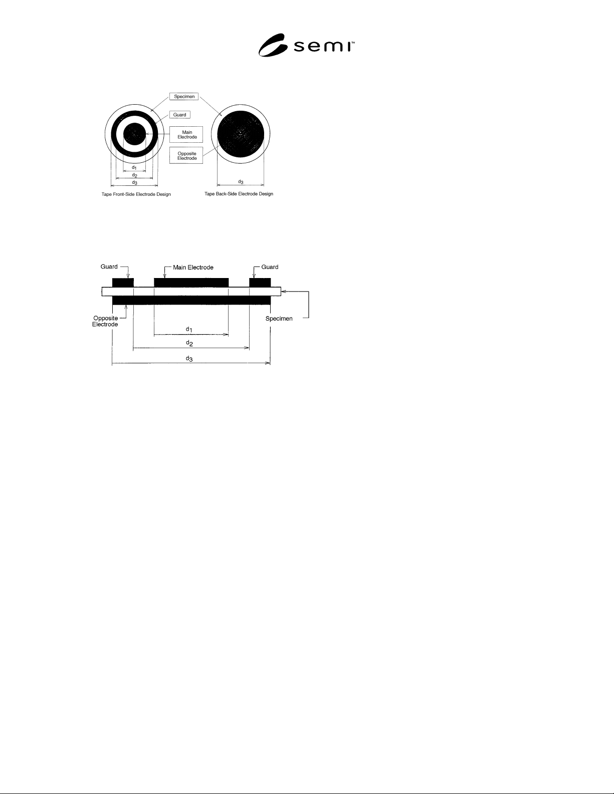
Electrodes are formed by conductive epoxy printing or
aluminum evaporation shown in Figures 2 and 3.
NOTE 1: The electrodes shall be formed on both sides of
tape.
NOTE 2: Suggested dimensions for the electrodes are shown
in Table 1 (d
1
– d
2
). They should be at least 10 times the tape
thickness.
Table 1 Suggested Dimension of Electrodes
Suggested Dimension (for Tape Thickness
of 0.063–0.077 mm)
Value
d
1
18 mm
d
2
20 mm
d
3
30 mm
6.2 Connect the specimen in the position of C
x
as
shown in Figure 1, and balance the bridge by adjusting
the measuring condenser C
s
and conductance shifter. In
this state, measure the C
s
value, the conductance value
between “m” and “d”, resistance between “I” and “m”,
and “r” and “m” of the conductance shifter in Figure 1.
SEMI G75.11-0698 © SEMI 1998 2
Figure 2
Electrodes Formed on the Leadframe Tape
Figure 3
Electrode Connection

3
SEMI G75.11-0698 © SEMI 1998
6.3 Dielectric constant and dielectric dissipation factor should be calculated by the following equation:
ε
=
C
x
/C
o
tan
δ
= G
x
/2
π
fC
x
w
h
ere
:
ε
:
dielectric constant
tan
:
dielectric dissipation factor
C
x
:
capacity of measuring condenser
C
c
balances
C
o
:
electrostatic capacity for
ε
=1
calculated by the following equation using the area of
the main electrode and thickness of specimen
C
o
=
r
2
/3.6 t
where :
r
:
radius of main electrode
t
:
thickness of specimen
G
x
:
conductance of specimen calculated
by the following equation
G
x
=g
×
Sv/100
where :
g
:
conductance between "m" and "d"
of conductance shifter in Figure 1
Sv/100
:
resistance ration of conductance
shifter at balance
f
:
the frequency of measurement
:
the ratio of the circle's circumference
to its diameter
7 Related Documents
7.1 ASTM Specification
2
ASTM D 150-64T — Standard Test Methods for Dielectric Constant and Dissipation Factor of Insulating Materials
2 American Society of Testing and Materials, 100 Barr Harbor Drive, West Conshohoken, PA 19428-2959 (all cited standards may be found in
Volume 10.05 of the Annual Book of ASTM Standards)