semi合集-English.pdf - 第1930页
SEMI E54.1-1000 © SEMI 1996, 2000 36 7.4.5.1.1 Offset — An attribute which sp e c i fies the amount of offset correction bei ng appl ied to deriv e the value o f the “Value” attribute (inherited) of th e obj ect instance…
SEMI E54.1-1000 © SEMI 1996, 200035
7.4.4.1.5 DataUnits — An attribute which defines the
current units associated with “Value” attribute
(inherited) of the object instance.
7.4.4.1.6 AlarmSettleTime — An attribute which
specifies a time used in the determination of a
Controller object instance alarm exception condition.
This value is expressed in units of seconds. The
minimum allowable value for this attribute is specified
by the manufacturer. An out-of-range error will result
from an attempt to set this attribute to a value lower
than that specified as the minimum allowable.
7.4.4.1.7 AlarmErrorBand — An attribute which
specifies an amount by which the process variable may
not equal the setpoint used in the determination of a
Controller object instance alarm exception condition.
This value is expressed in units identified by the
“DataUnits” attribute and in a format specified by the
“DataType” attribute.
7.4.4.1.8 WarningSettleTime — An attribute which
specifies a time used in the determination of a
Controller object instance warning exception condition.
This value is expressed in units of seconds. The
minimum allowable value for this attribute is specified
by the manufacturer. An out-of-range error will result
from an attempt to set this attribute to a value lower
than that specified as the minimum allowable.
7.4.4.1.9 WarningErrorBand — An attribute which
specifies an amount by which the process variable may
not equal the setpoint used in the determination of a
Controller object instance warning exception condition.
This value is expressed in units identified by the
“DataUnits” attribute and in a format specified by the
“DataType” attribute.
7.4.4.2 Controller Class Services — No C class
common services are defined. Note that the C class
inherits all AE class services.
7.4.4.3 Controller Class Behavior — The following
applies to C class behavior:
The controller element uses the value of the Process-
Variable and Setpoint attributes and determines the
error signal. It then adjusts the ControlVariable attribute
value as necessary and appropriate to minimize this
error signal. The method of, and conditions for,
adjustment are beyond the scope of this document.
Note that the C class inherits all AE class-defined
behavior.
7.4.5 Sensor-Analog Input (SAI) Class — The SAI
class at the third level of the active element
generalization hierarchy contains structure and behavior
common to all analog input sensor element instances in
a device. Note that, as discussed in Section 7.4, since
this is the lowest level of class description in the
generalization hierarchy for this device element type
(see Figure 7), object instances can be created as
instances of this class type.
7.4.5.1 Sensor-Analog Input Class Attributes — All
required and “common optional” SAI class attributes
are listed in Table 38 and described below. For an
explanation of the table format, see Section 7.3.1. Note
that the SAI class also inherits all AE and S class
attributes.
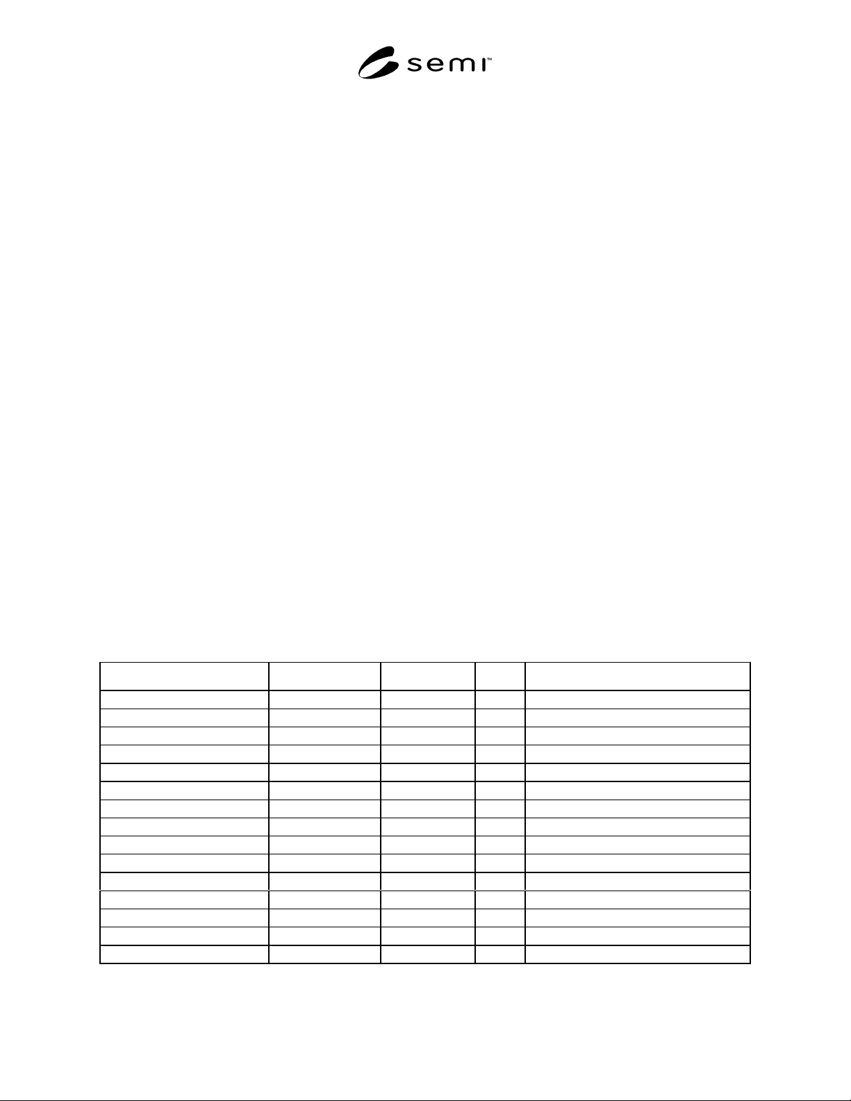
Table 38 SAI Class Attributes*
Attribute Name Attribute Identifier Access (Network) Rqmt Form
Offset SaiA64 RW N Context-Specific
Gain SaiA65 RW N Context-Specific
DataType SaiA66 RW N Context-Specific
DataUnits SaiA67 RW N Context-Specific
SafeState SaiA68 RW N Enumerated Byte
EnableReportDelta SaiA69 RW N Boolean
ReportDelta SaiA70 RW N Context-Specific
EnableReportROC SaiA71 RW N Boolean
ReportROC SaiA72 RW N Context-Specific
AlarmTripPointHigh SaiA73 RW N Context-Specific
AlarmTripPointLow SaiA74 RW N Context-Specific
AlarmHystersis SaiA75 RW N Context-Specific
WarningTripPointHigh SaiA76 RW N Context-Specific
WarningTripPointLow SaiA77 RW N Context-Specific
WarningHystersis SaiA78** RW N Context-Specific
* A “Definition” column is not included. For attribute definitions, see text.
** ID’s SaiA78 through SaiA127 are reserved for future Sai class attribute definition.
SEMI E54.1-1000 © SEMI 1996, 2000 36
7.4.5.1.1 Offset — An attribute which specifies the
amount of offset correction being applied to derive the
value of the “Value” attribute (inherited) of the object
instance. It is expressed in terms of the units specified
by the “DataUnits” attribute.
7.4.5.1.2 Gain — An attribute which is used to define
the range of the “Value” attribute (inherited) of the
object instance. The method of conveying this range
with this attribute is beyond the scope of this document.
7.4.5.1.3 DataType — An attribute which defines the
format of the data associated with “Value” attribute
(inherited) of the object instance.
7.4.5.1.4 DataUnits — An attribute which defines the
current units associated with “Value” attribute
(inherited) of the object instance.
7.4.5.1.5 SafeState — An attribute which defines the
Value (inherited attribute) to be reported by the object
instance when it is in a non-OPERATING state. The
enumeration of the SafeState attribute is given in Table
39.
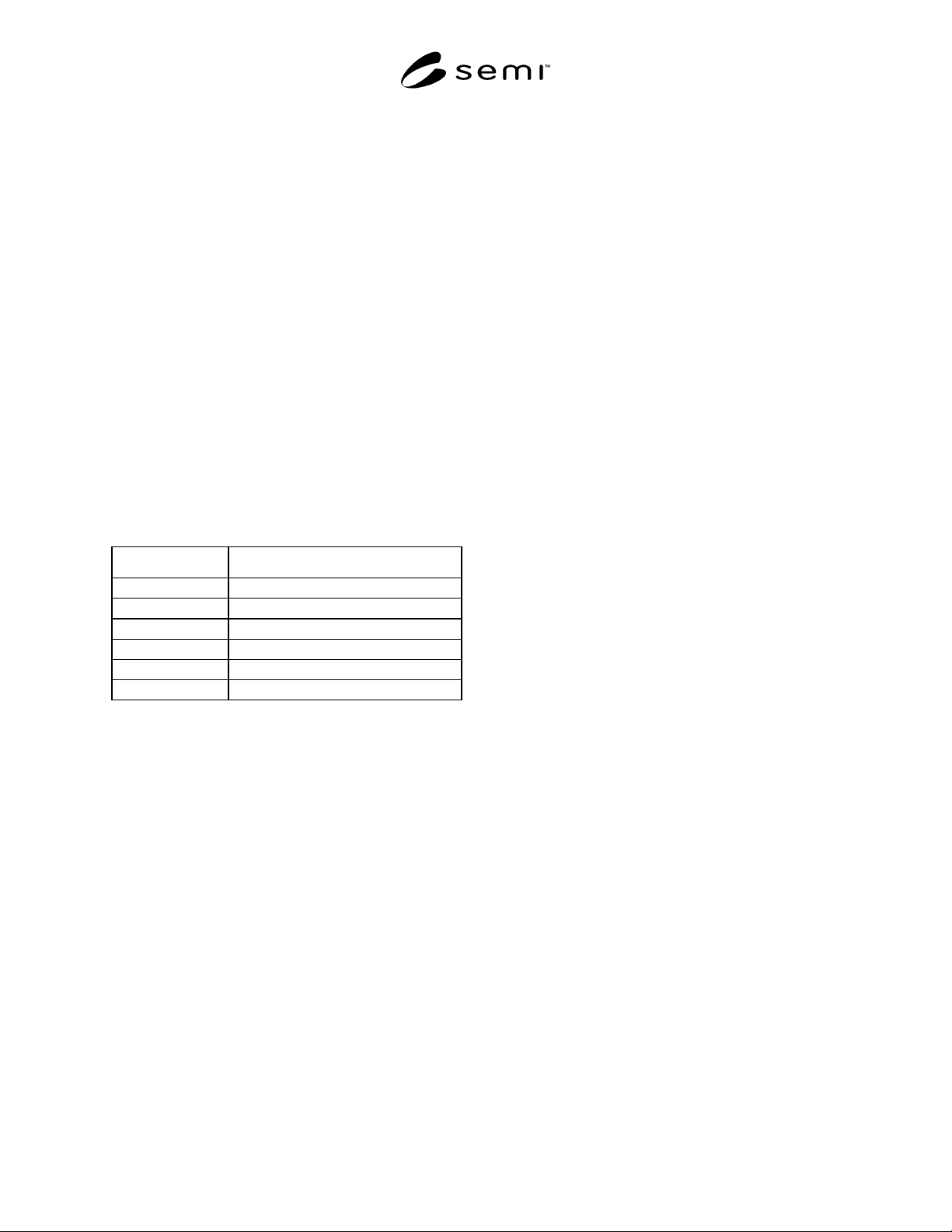
Table 39 SafeState Attribute Values
Attribute Value DM Object State
0Zero
1 Full-Scale
2LVV
3 Undefined
4 – 63 Reserved
64 – 255 Open
7.4.5.1.6 EnableReportDelta — An attribute which
enables the reporting of the attribute “Value” based on
the “ReportDelta” attribute value (see below); a value
of TRUE signifies that reporting using the
“ReportDelta” method is enabled.
7.4.5.1.7 ReportDelta — The value of this attribute
indicates the amount by which the sensor value
(indicated by the “Value” attribute (inherited)) must
change before it is published. When the value of the
EnableReportDelta attribute indicates that this method
of reporting is “enabled”, and when the value of the
“Value” attribute changes by an amount in excess of the
amount indicated by the ReportDelta attribute value, the
object will publish the Value attribute.
7.4.5.1.8 EnableReportROC — The Enable
ReportROC (rate of change) attribute enables the
reporting of the attribute “Value” based on the
“ReportROC” attribute value (see below); a value of
TRUE signifies that reporting using the rate of change
method is enabled.
7.4.5.1.9 ReportROC — The value of this attribute
indicates the rate by which the sensor value (indicated
by the “Value” attribute (inherited)) must change before
it is published. The attribute value context is
DataUnits/Time; the specific context of DataUnits is
defined in the DataUnits attribute, while the unit of
Time is context-specific. When the value of the
EnableReportDelta attribute indicates that this method
of reporting is “enabled”, and when the value of the
“Value” attribute changes at a rate in excess of the
amount indicated by the ReportDelta attribute value, the
object will publish the Value attribute.
7.4.5.1.10 AlarmTripPointHigh — An attribute which
specifies the value above which the object instance
“Value” attribute (inherited) value must be to generate
an alarm status indication. The behavior associated with
the generation of an alarm status indication (beyond
that described in Section 7.4.1.3) is beyond the scope of
this document.
7.4.5.1.11 AlarmTripPointLow — An attribute which
specifies the value below which the object instance
“Value” attribute (inherited) value must be to generate
an alarm status indication. The behavior associated with
the generation of an alarm status indication (beyond
that described in Section 7.4.1.3) is beyond the scope of
this document.
7.4.5.1.12 AlarmHystersis — An attribute which
specifies the amount of hysteresis to be applied in the
clearing of an alarm condition. For example: a Trip
Point High value of 100 with a hysteresis value of 2
will result in an exception condition being set when the
Value attribute exceeds 100 in the positive direction
and cleared when the Value attribute exceeds 98 in the
negative direction. Similarly, a Trip Point Low value of
100 with a hysteresis value of 2 will result in an
exception condition being set when the Value attribute
exceeds 100 in the negative direction and cleared when
the Value attribute exceeds 102 in the positive
direction. The behavior associated with the generation
and clearing of exception conditions is beyond the
scope of this document.
7.4.5.1.13 WarningTripPointHigh — An attribute
which specifies the value above which the object
instance “Value” attribute (inherited) value must be to
generate a warning status indication. The behavior
associated with the generation of a warning status
indication is beyond the scope of this document.
7.4.5.1.14 WarningTripPointLow — An attribute
which specifies the value below which the object
instance “Value” attribute (inherited) value must be to
generate a warning status indication. The behavior
associated with the generation of a warning status
indication is beyond the scope of this document.
SEMI E54.1-1000 © SEMI 1996, 200037
7.4.5.1.15 WarningHystersis — An attribute which specifies the amount of hysteresis to be applied in the clearing
of an alarm condition (see Section 7.4.5.1.12). The behavior associated with the generation and clearing of exception
conditions is beyond the scope of this document.
7.4.5.2 Sensor-Analog Input Class Services — No SAI class common services are defined. Note that the SAI class
inherits all AE and S class services.
7.4.5.3 Sensor-Analog Input Class Behavior — No SAI class common behavior is defined. Note that the SAI class
inherits all AE and S class-defined behavior.
7.4.6 Sensor-Binary Input (SBI) Class — The SBI class at the third level of the active element generalization
hierarchy contains structure and behavior common to all binary input sensor element instances in a device. Note
that, as discussed in Section 7.4, since this is the lowest level of class description in the generalization hierarchy for
this device element type (see Figure 7), object instances can be created as instances of this class type.
7.4.6.1 Sensor-Binary Input Class Attributes — All required and “common optional” SBI class attributes are listed
in Table 40 and described below. For an explanation of the table format, see Section 7.3.1. Note that the SBI class
also inherits all AE and S class attributes.
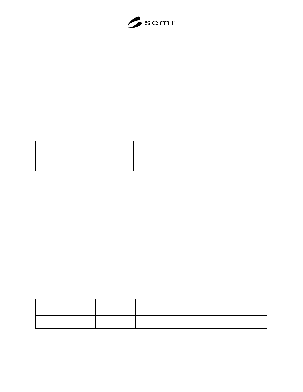
Table 40 SBI Class Attributes*
Attribute Name Attribute Identifier Access (Network) Rqmt Form
DebounceControl SbiA64 RW N Context-specific
AlarmState SbiA65 RW N Boolean
WarningState SbiA66** RW N Boolean
* A “Definition” column is not included. For attribute definitions, see text.
** ID’s Sbi67 through SbiA127 are reserved for future Sbi class attribute definition.
7.4.6.1.1 DebounceControl — This attribute is used to control sensitivity to ‘false’ transitions. The method of
utilization of this attribute for debounce control is application-specific.
7.4.6.1.2 AlarmState — The value of the Value attribute (i.e., TRUE or FALSE) that will cause an alarm condition.
7.4.6.1.3 WarningState — The value of the Value attribute (i.e., TRUE or FALSE) that will cause a warning
condition.
7.4.6.2 Sensor-Binary Input Class Services — No SBI class common services are defined. Note that the SBI class
inherits all AE and S class services.
7.4.6.3 Sensor-Binary Input Class Behavior — No SBI class common behavior is defined. Note that the SBI class
inherits all AE and S class-defined behavior.
7.4.6.4 Sensor-Enumerated Input Class Services — No SEI class common services are defined. Note that the SEI
class inherits all AE and S class services.
7.4.6.5 Sensor-Enumerated Input Class Attributes — All required and “common optional” SEI class attributes are
listed in Table 41 and described below. For an explanation of the table format, see Section 7.3.1. Note that the SEI
class also inherits all AE and S class attributes.
Table 41 SEI Class Attributes*
Attribute Name Attribute Identifier Access Network Rqmt Form
DebounceControl SeiA64 RW N Context-Specific
AlarmState SeiA65 RW N Enumerated
WarningState SeiA66 RW N Enumerated
* A “Definition” column is not included. For attribute definitions, see text.
7.4.6.5.1 DebounceControl — This attribute is used to control sensitivity to ‘false’ transitions. The method of
utilization of this attribute for debounce control is application-specific.