semi合集-English.pdf - 第7083页
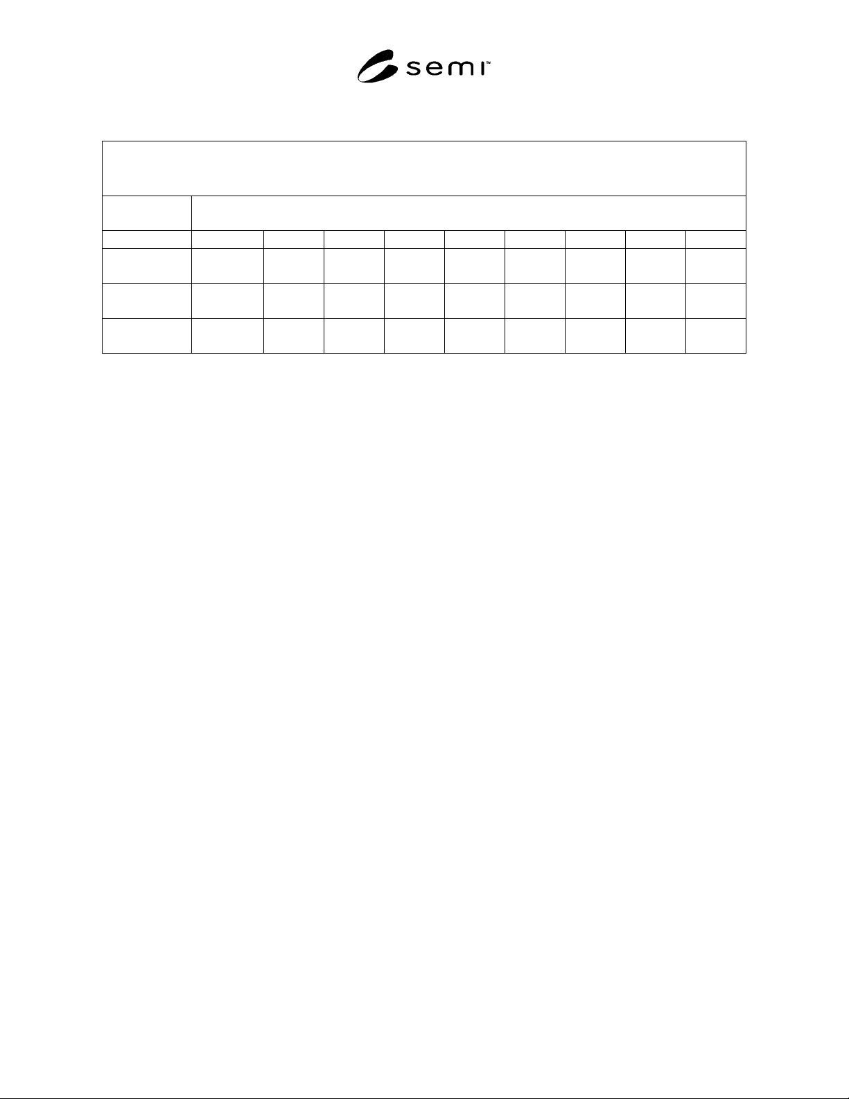
SEMI S18-1102 © SEMI 2002 21 Table R2-1 Silane Flow Rates Thr ough Restricted Flow Orifices Based on the Predictionsfrom the Factory Mutual Research Model Silane Flow Rate [scfm ] (Source Temperature: 77°F; Downstream Pr…
SEMI S18-1102 © SEMI 2002 20
RELATED INFORMATION 2
EXAMPLES OF CALCULATIONS FOR MAXIMUM POTENTIALS FOR
SILANE FAMILY GASES
NOTICE: This Related Information is not an official balloted part of SEMI S18. It is included to assist the
user of the document in understanding effective control systems. Publication is authorized by vote of the responsible
committee.
R2-1 Release Potentials
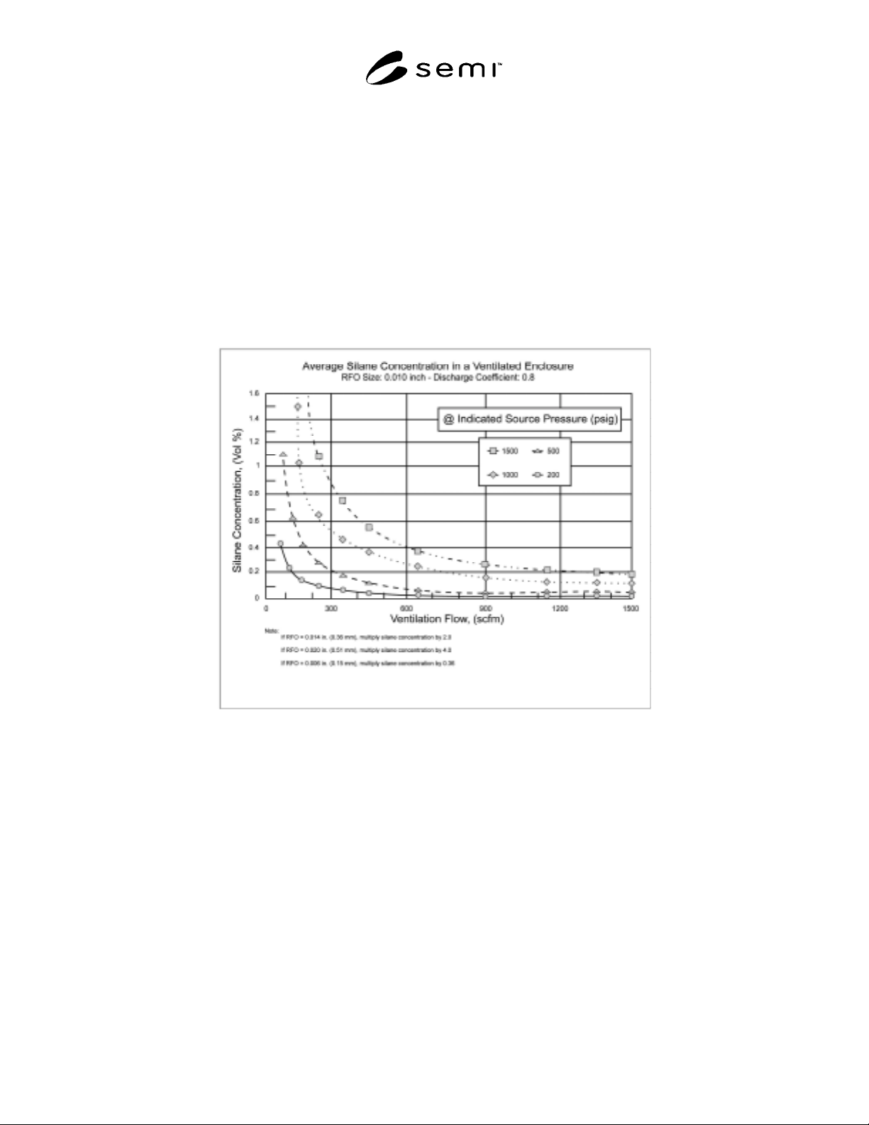
R2-1.1 In gas cabinets, size the ventilation system to limit the maximum concentration of silane inside the cabinet
to 0.4 percent by volume. Base the maximum concentration of silane inside the gas cabinet on the continuous release
of SiH
4
at a standard volumetric flow rate given by the size of the RFO in the discharge line and the maximum SiH
4
gas cylinder storage pressure (see Table R2-1). For a 0.4 percent concentration, the required ventilation airflow rate
can be estimated from Figure R2-1.
© 2001 Factory Mutual Insurance Company. Reprinted with permission from FM Global Property Loss Prevention Data Sheet 7-7
‘Semiconductor Fabrication Facilities’
Figure R2-1
Average Silane Concentration in a Ventilated Enclosure
SEMI S18-1102 © SEMI 2002 21
Table R2-1 Silane Flow Rates Through Restricted Flow Orifices Based on the Predictionsfrom the Factory
Mutual Research Model
Silane Flow Rate [scfm]
(Source Temperature: 77°F; Downstream Pressure: 0 psig; Discharge Coefficient: 0.8)
RFO Dia.
in. (mm)
Source Pressure [psig]
1500 1200 1000 800 600 400 200 100 50
0.020
(0.51)
10.0 7.88 6.04 4.34 3.02 1.92 0.949 0.497 0.288
0.014
(0.36)
4.91 3.86 2.96 2.13 1.48 0.941 0.465 0.243 0.136
0.010
(0.25)
2.50 1.97 1.51 1.08 0.755 0.480 0.237 0.124 0.069
© 2001 Factory Mutual Insurance Company. Reprinted with permission from FM Global Property Loss Prevention Data Sheet 7-7
‘Semiconductor Fabrication Facilities’
R2-2 Explosion Potentials
R2-2.1 Silane Ventilated Enclosure Example
R2-2.1.1 Consider the case of a ventilated enclosure of 25.9 ft (0.73 m) volume, swept by a ventilation flow of 450
scfm (12,744 lpm). Silane is supplied to the enclosure by a 1/4-in. (6.3 mm) (OD) line at a regulated pressure of 50
psig (3.4 bar). This line is in turn fed from a source at 1450 psig (100 bar), through a 10-mil restricted flow orifice
(RFO), located at a distance of 80 ft (24.4 m) from the ventilated enclosure. Safe operation of the system is
determined by the evaluation of two conditions:
• the magnitude of the initial silane inventory in the 1/4-in. (6.3 mm) line relative to the size of the enclosure, and
• the magnitude of the RFO-controlled flow relative to the ventilation in the enclosure. The first condition
determines the severity of a potential ignition transient at flow start-up. The second provides a measure of the
pressure development at flow shut-off.
R2-2.2 The standard silane inventory in the line is calculated by first determining the volume of the line [assume
0.035 in. (0.9 mm) wall thickness]:
V
line
= π / 4 (0.25-2×0.035)
2
× 80 × 12 = 24.43 in
3
The silane volume, when expanded to standard conditions, is given by (cf. Eq. 1):
∆Vstd = 24.43 × 0.0708 × 50 (1 + 8.19 10
–7
×
50
2
) = 86.66 in
3
= 0.05 ft
3
The ratio of the volume of the enclosure to the standard volume of silane is:
Vencl / ∆Vstd = 25.9 / 0.05 = 518
R2-2.3 Since this value is greater than 100, the situation is acceptable from the point of view of potential pressure
transients caused by ignition of the release at flow startup.
R2-2.4 Verifying the second condition requires calculating the RFO-controlled flow. By interpolation of the data in
Table 2, the flow through a 10-mil orifice from a source at 1450 psig (100 bar) is estimated to be equal to 2.41 scfm
(68.25 lpm). Since the maximum silane flow rate that can be accepted for a ventilation of 450 scfm (12,744 lpm) is
1.8 scfm (51 lpm) (450/250, see recommendation 3 above), this situation is not acceptable. It would become
acceptable if the ventilation flow was increased to 600 scfm (16,992 lpm) (2.41 ´ 250) or if the explosion venting
conditions shown in Figures R2-2a and R2-2b were to be satisfied.
SEMI S18-1102 © SEMI 2002 22
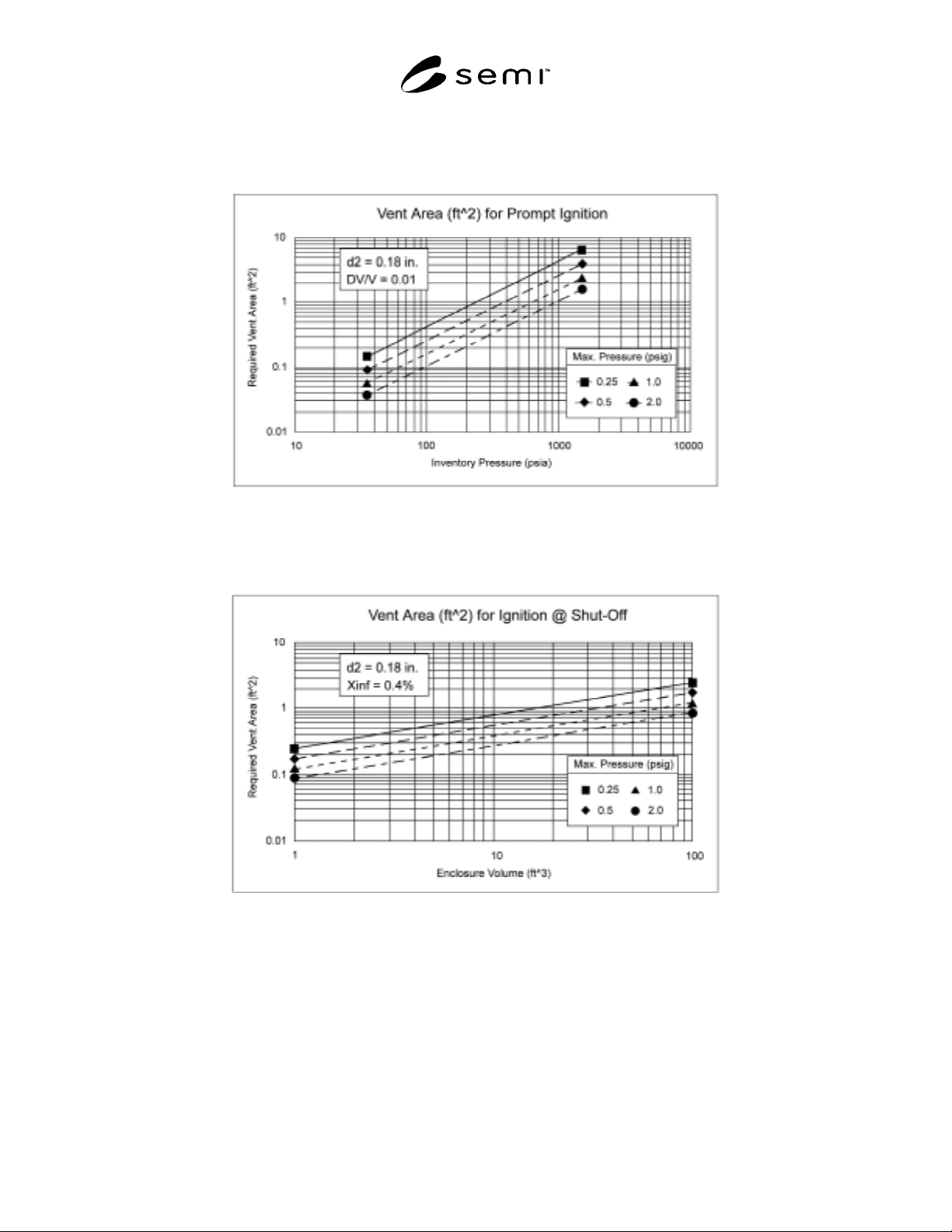
R2-2.5 Provide explosion venting for gas cabinets and enclosures to limit overpressure inside gas cabinets and
enclosures to 0.25 psig (1.7 kPag). Explosion venting can be provided by door panels, windows, louvers or exhaust
duct openings. Size explosion venting to satisfy both the requirements for line inventory pressure (Figure R2-2a) and
for the volume of the enclosure (or cabinet) (Figure R2-2b).
© 2001 Factory Mutual Insurance Company. Reprinted with permission from FM Global Property Loss Prevention Data Sheet 7-7
‘Semiconductor Fabrication Facilities’
Figure R2-2a
Vent Area Requirement for Prompt Ignition of Silane Releases as a Function of Initial Line Pressure
© 2001 Factory Mutual Insurance Company. Reprinted with permission from FM Global Property Loss Prevention Data Sheet 7-7
‘Semiconductor Fabrication Facilities’
Figure R2-2b
Vent Area Requirements for Ignition of Silane Releases at Shut-Off as a Function of Enclosure Volume