semi合集-English.pdf - 第5868页
SEMI P35-0704 © SEMI 2000, 2004 3 boxes is the combined uncertain ties of the measured centroid position of the mean linewidth bounding box and of the positions of the line’s edg es between these linewidth bounding box e…
SEMI P35-0704 © SEMI 2000, 2004 2
Figure 1
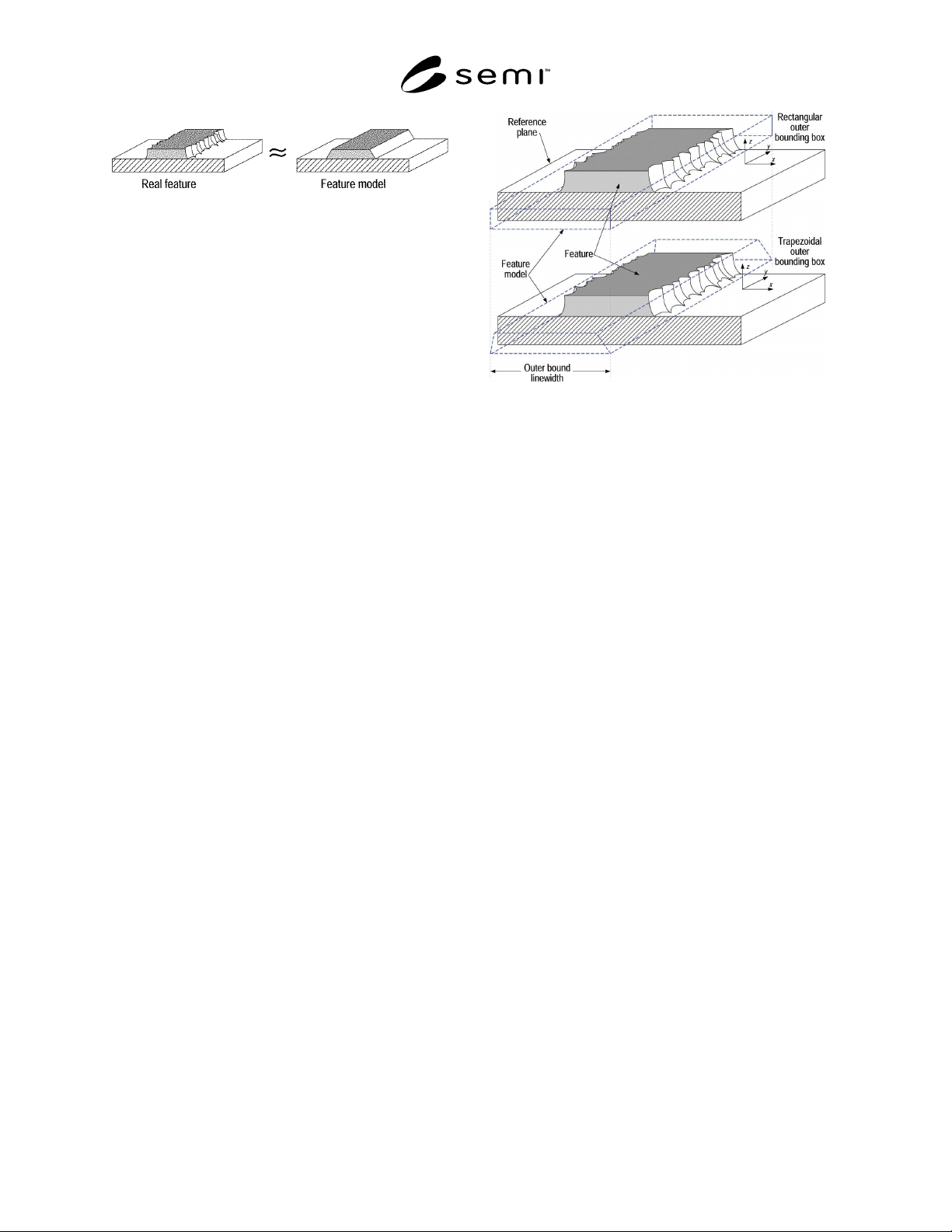
The Feature Model Approximates the Size and
Shape of the Feature
4.3.1 The feature model may be further abstracted to
suit the purpose of the measurement by defining
bounding boxes to represent the inner and outer limits
on the space occupied by the feature. In the nonexistent
case of an ideal feature, the feature, the feature model,
and the bounding boxes would all coincide.
4.4 The aim of the approach embodied here is to
facilitate interpretation of metrology results for a
feature (and the feature’s subsequent performance —
see section A1) in the most realistic terms, and in light
of any possible additional knowledge about that feature.
4.5 There are many possible reasons for measuring a
feature’s size or placement. Consequently the following
definitions may include options or alternatives, to be
selected by the user to best fit the purpose of the
measurement.
5 Definitions
5.1 Defined terms appearing in the definitions of other
terms are italicized. Where more than one definition is
given for a term, the one most appropriate to the
application is to be chosen. Some of these definitions
describe certain usage options as “the default.” That
option is assumed to apply unless otherwise specified.
5.1.1 bounding box — a user-specified geometric shape
with a planar face lying in the reference plane and with
user-specified orientation in the reference plane,
intended to represent limits or bounds on the position
and size of the feature. See Figure 2 for an example.
The bounding box need not be rectangular.
Figure 2
Two Possible Bounding Box Choices for a Line
Feature
NOTE 1: The term “bounding box” is used here for
convenience, but the word “box” may not always be
considered appropriate. Terms like “bounding figure” or
“bounding surface” may be used instead, if desired. A
bounding box may coincide with a feature model.
5.1.1.1 outer bounding box — smallest bounding box
encompassing the feature.
5.1.1.2 best fit bounding box — bounding box best
fitting the feature, with user-defined criteria of best fit.
5.1.2 calibration — set of operations that establish,
under specified conditions, the relationship between
values of quantities indicated by a measuring
instrument or measuring system, or values represented
by a material measure or reference material, and the
corresponding values realized by standards [reference
Section 6.1].
5.1.3 centerline — (a) The locus of the centroids of
successive line segments, in the limit as the segment
length vanishes. (b) a line or surface midway between
opposing feature edges.
5.1.4 centroid — The geometrical center of an object.
The coordinates of the centroid of an object are C
u
=
∫∫∫u dV / ∫∫∫dV, where the integral is over the volume V
of the object and u can be x, y, or z.
5.1.4.1 centroid measurement uncertainty — parameter
that characterizes the dispersion of the values that could
reasonably be attributed to the position of the centroid
or the placement of an object in the reference plane
coordinate system (see measurement uncertainty).
NOTE 2: The edges of the feature form part of the boundary
of the integral defining the centroid; edge position uncertainty
leads to integral boundary uncertainty and thus to centroid
uncertainty. The centroid measurement uncertainty of a
feature described by inner and outer linewidth bounding
SEMI P35-0704 © SEMI 2000, 2004 3
boxes is the combined uncertainties of the measured centroid
position of the mean linewidth bounding box and of the
positions of the line’s edges between these linewidth
bounding boxes, taking into account possible opposite edge
correlations. (These correlations can result in feature
placement or pitch uncertainty that is less than the
corresponding linewidth uncertainty because many features
have some degree of mirror image symmetry between
opposite edges.)
5.1.5 feature (lithographic) — region within a single
continuous boundary, and attached to a reference plane,
that has a defining physical property (parameter) that is
distinct from the region outside the boundary. [Adapted
from SEMI P28.]
NOTE 3: In general a feature is a 3-dimensional object, but
some features can be adequately modeled as 2-dimensional
objects.
5.1.5.1 feature boundary — surface defined by a user-
specified property, such as a threshold, maximum
gradient, etc., of the parameter distinguishing that
feature from its surroundings. Open features, such as
vias or spaces between lines, may be bounded in height
by an additional plane parallel to the reference plane.
5.1.5.2 feature edge — that part of the feature
boundary used to define the feature size or linewidth.
The criteria used must be specified.
5.1.5.3 feature height — dimension of the specified
bounding box perpendicular to the reference plane.
May also refer to feature depth below the substrate, as
in contact holes. Although feature height is sometimes
referred to as feature thickness, this usage is not
recommended because “thickness” sometimes alludes
to “width.”
5.1.5.4 feature model — a solid geometrical shape,
with well-defined parameters, e.g., length, width,
height, centroid, etc. (Figure 1), meant to approximate
the actual shape of a feature boundary.
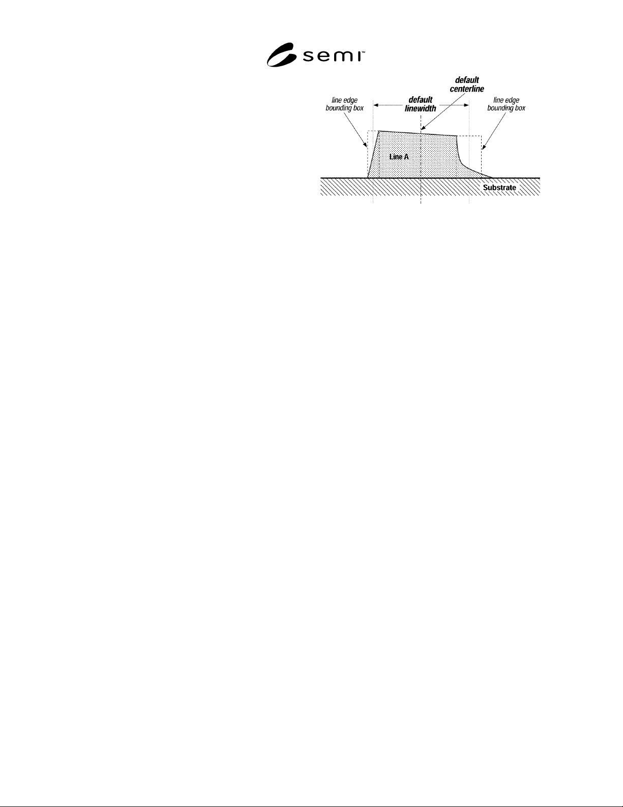
Figure 3
Examples of line edge bounding boxes and the
resulting default centerline and linewidth. Since the
top of Line A is not parallel to the substrate, the
generalized linewidth bounding box definition (b) is
used. Line edge asperities at the substrate were
judged not to be relevant to the function of this
feature and were excluded from the outer line edge
bounding boxes.
NOTE 4: A rectangular solid is often used to represent a line;
a different extruded polygon may better represent the shape of
the line. A hemisphere may best represent a solder bump.
The more complex the model, more degrees of freedom are
available to better fit the model to the feature, and more
dimensional parameters are needed to describe the feature’s
size. The feature model is a simplified geometric
approximation of the actual feature, the bounding boxes
represent limits on the space occupied by the feature model.
The size or position of a feature can be described by the size
or position of the feature model with appropriate
uncertainties, or by the sizes or positions of the bounding
boxes. This choice is left to the user, and in many of these
definitions the terms can be interchanged. Bounding boxes are
useful because they make the measurement uncertainty
explicit, and because an application of the measurement data
may require only inner or outer bounds.
5.1.5.5 feature placement — (a) coordinates describing
the position of the centroid of the specified bounding
box projected onto the reference plane relative to a
coordinate system in that plane. (b) coordinates
describing positions of the feature’s edges.
5.1.5.6 feature size — dimensions of the specified
feature model or bounding box.
5.1.5.7 nominal feature size — the intended or
specified dimension of a feature.
SEMI P35-0704 © SEMI 2000, 2004 4
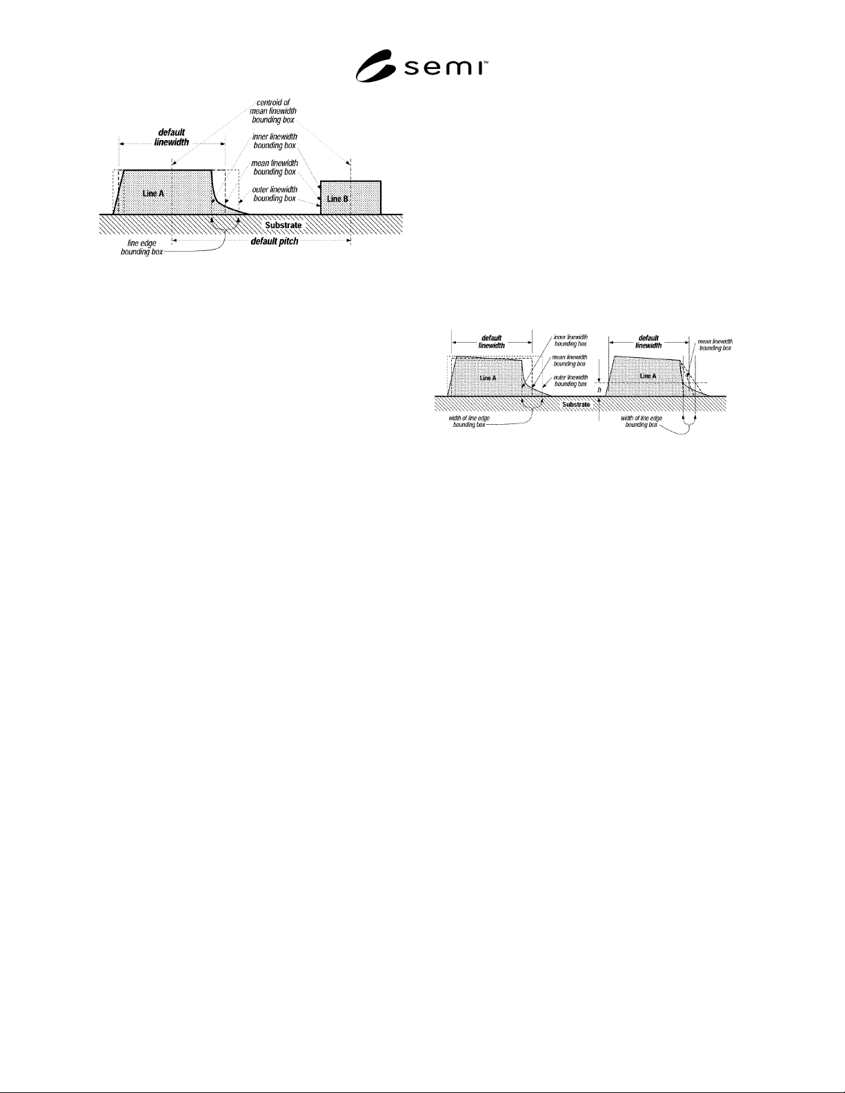
Figure 4
Examples of inner, outer, and mean linewidth
bounding boxes, and the corresponding default
linewidth and pitch. Line edge asperities at the
substrate were judged not to be relevant to the
function of this feature and were excluded from the
outer linewidth bounding box.
5.1.6 line edge bounding box — (a) the region, for each
edge, between specified inner and outer linewidth
bounding boxes encompassing the edge of the feature.
(b) user-specified bounding box intended to encompass
the feature edge. See Figure 3.
NOTE 5: The underlying concept here is the same as for a
feature bounding box; only the perspective is different. If a
feature is described using a pair of inner and outer linewidth
bounding boxes, then the widths of the corresponding line
edge bounding boxes illustrate the component of the linewidth
measurement uncertainty arising from the definition of the
feature’s edge, and “the linewidth bounding box” describing
the feature is taken to mean the mean linewidth bounding box
by default.
5.1.7 line edge position — expectation value of the
position of the edge within the line edge bounding box
used to define the linewidth. If the probability
distribution of the edge within the line edge bounding
box is symmetric, this will be at the center of the line
edge bounding box.
5.1.8 linewidth bounding box — (a) if the feature
height is unambiguous, a specified rectangular
bounding box constrained to the line height and
bounding a specified line length segment; (b)
appropriate parameters describing a different bounding
box. Additional constraints, such as orientation parallel
to a defined length direction, may be placed on the
bounding box. See Figure 4.
5.1.8.1 linewidth — (a) width of a specified linewidth
bounding box. See Figures 3 and 4. (b) distance
between the two opposing line edge positions of a
feature. See Figures 5, 6, and 7.
NOTE 6: Linewidth is sometimes referred to as critical
dimension or CD.
5.1.8.2 best fit linewidth — width of constrained best
fit linewidth bounding box.
5.1.8.3 mean linewidth bounding box — a bounding
box between inner and outer linewidth bounding boxes,
whose right and left edge positions at any height above
the substrate are the means of the edge positions of the
inner and outer linewidth bounding boxes at that height.
See Figues 4 and 5.
5.1.8.4 inner bound linewidth — width of largest
linewidth bounding box entirely inside the line segment.
Its width is the smallest linewidth that is ordinarily
associated with the feature.
Figure 5
Example of using rectangular and trapezoidal
linewidth bounding boxes to describe Line A in
Figure 4. The trapezoidal case requires an
additional specification for the linewidth, such as at
the distance h above the reference plane, but it
probably better represents the real feature and the
width of its line edge bounding box is smaller.
5.1.8.5 outer bound linewidth — width of smallest
linewidth bounding box encompassing the line segment.
Line edge asperities may reasonably be excluded. Its
width is the largest linewidth that is ordinarily
associated with the feature.
5.1.8.6 section linewidth — width of the planar
rectangle defining the intersection of a linewidth
bounding box and a plane parallel to and a specified
distance from the reference plane.
5.1.8.7 linewidth measurement uncertainty —
parameter that characterizes the dispersion of the values
that could reasonably be attributed to the linewidth of
an object (see measurement uncertainty).
5.1.8.7.1 One option here is to choose inner and outer
linewidth bounding boxes so that there is a 95% chance
that the line’s true edges lie between them. Then the
linewidth measurement uncertainty will be the
combined uncertainties of the measured width of the
mean linewidth bounding box and of the positions of
the line’s edges between these linewidth bounding
boxes, taking into account possible right-left edge
correlations. This option is the default.