semi合集-English.pdf - 第4219页
SEMI F74-1103 © SEMI 2002, 2003 6 (mm) Figure 2 Dimension of the We dge-Sha ped Indent er Figure 3 Wedge and Test Sam ple (Component or Subs trate) Maximum rated working pressure or 5000 PSI GAS SUPPL Y VENT TO VACUUM IS…
SEMI F74-1103 © SEMI 2002, 2003 5
7.9.2 A material testing machine is used to make a
defect on the surface. In place of a pyramid-shaped
indenter for hardness measurement, a wedged shaped
indenter, specifically designed for this test, is installed
in the adjustable-load hardness measurement equipment
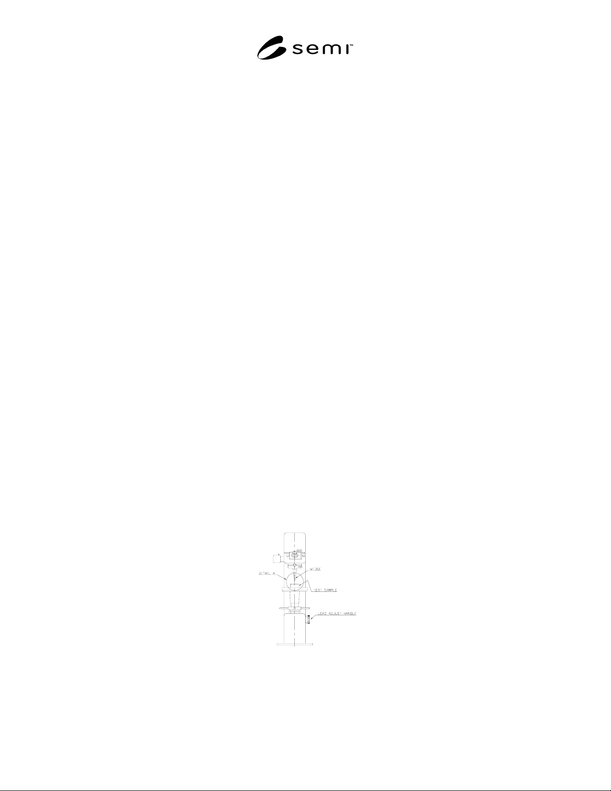
shown in Figure 1 and is used to make a surface defect
on test sample.
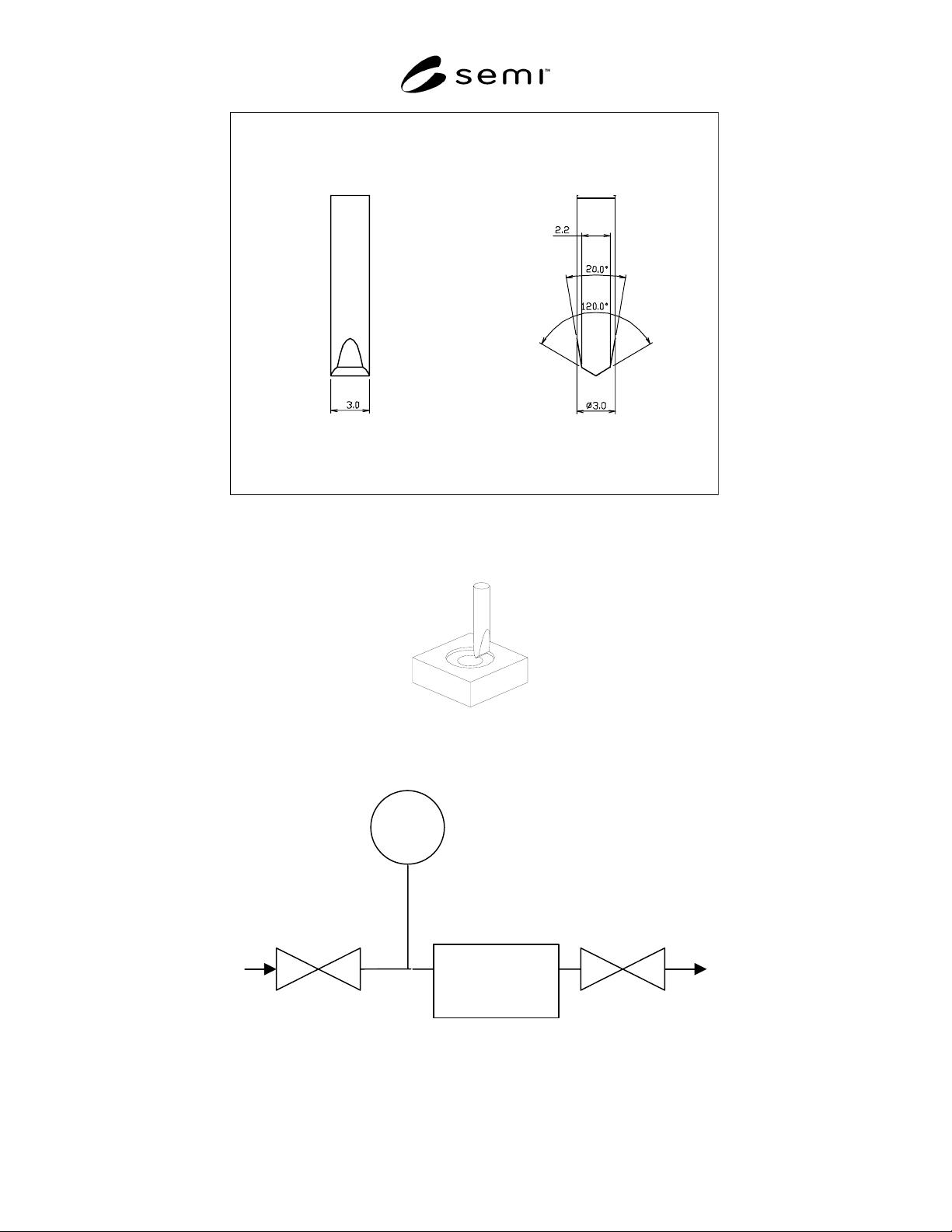
7.9.3 The indenter shall meet the dimensional
requirement shown in Figure 2. The indenter shall have
a minimum hardness of 500 Vickers.
7.9.4 This test defaces only the seal face of the
component, and determines the size of the surface
defect as well as the corresponding leak. In this way,
the degree of weakness of the component’s seal face, as
well as the extent to which the leak can be stopped
depending on defect size, can be determined, making it
possible to evaluate the robustness of the sealing
technology being tested.
7.9.5 Equipment shown in Figure 1 and Figure 2 is
used to make a defect on the surface of the seal face of
the component or substrate.
7.9.6 Load levels are 2, 4, 6, 8 kgf, (19.61, 39.23.
58.84, 78.45 N) and add 2 kgf (19.61 N) incrementally
until leaking occurs. The test sample should be
tightened according to the manufacturer’s installation
manual.
7.9.7 A leak test is performed on the sample according
to the procedure in SEMI F1. As this document is a test
method, not a specification, only the procedure in SEMI
F1 applies.
7.9.8 Correlation between the load and the leak is
determined.
7.9.9 Surface defect size (depth and width) is measured
using surface roughness measuring equipment for
reference.
7.10 Particle Cleanliness After Seal Make-up
7.10.1 The purpose of this test is to verify the particles
generated during a sealing-system compression cycle.
This test involves testing for particles in situ, while
compressing a sealing system.
7.10.2 Test per SEMASPEC 90120390B-STD. Use a
flow-through testing apparatus that is seal-specifically
designed for use in this test, in place of a valve.
7.10.3 Testing must be performed in a Class 100 (or
better) environment in order to obtain low background
counts before the seals are tightened to the substrate.
7.10.4 Follow test protocol in Test Method for Particle
Contribution (see Related Documents) with the
exception that a flow-through bypass fixture must be
attached “finger-tight” to a test substrate before
obtaining a background count.
7.10.5 The testing apparatus with the seals to be tested
must be purged with 0.01 µm filtered gas for sufficient
time so as to remove all inherent particles present
during installation.
7.10.6 Once the lowest possible background count has
been generated, the flow-through test device must be
tightened to the seal manufacturer’s
specifications
while gathering particle counts from the particle
counter. It is recommended that the counts are recorded
via a data acquisition device to allow the user to
compress the seals while the particles are being
recorded.
7.10.7 This test is for comparison purposes only
between data generated at a common facility with
common test setup.
Figure 1
Load Adjustable Hardness Measuring Equipment
SEMI F74-1103 © SEMI 2002, 2003 6
(mm)
Figure 2
Dimension of the Wedge-Shaped Indenter
Figure 3
Wedge and Test Sample (Component or Substrate)
Maximum
rated
working
pressure or
5000 PSI
GAS
SUPPLY
VENT TO
VACUUM
ISOLATION
VALVE
PT
TEST
SAMPLE(S)
ISOLATION
VALVE
Figure 4
Pressure Cycling Test Rig
SEMI F74-1103 © SEMI 2002, 2003 7
7.11 Corrosion Testing
7.11.1 Due to the lack of proven, standardized test
methods for quantifying the performance of gas
systems in corrosive environments, this document can
only reference two applicable test procedures for use to
supply qualitative information relating to the
performance of gas system metal seals under corrosive
serve: SEMI F77 and SEMASPEC 97043272A-TR (see
Related Documents). It will be the responsibility of the
requesting party to define the specific testing and
acceptance criteria for this type of evaluation.
7.12 Pressure Cycling Test
7.12.1 Assemble the test sample(s) into the test rig
shown in Figure 4 per the manufacturer’s instructions.
7.12.2 Cycle the test sample(s) for a total of 250,000
cycles. The following represents one cycle:
7.12.2.1 Apply the manufacturer’s maximum rated
working pressure + /- 2% or 5000 + /- 100 psig,
whichever is less.
7.12.2.2 Maintain pressure for at least 1 second after
the transducer indicates that the pressure requirement
has been achieved.
7.12.2.3 Vent the pressure to 74.5 KPa or less.
7.12.2.4 Maintain the vacuum for at least 1 second
after the transducer indicates that vacuum requirement
has been achieved.
7.12.3 Leak test per Section 7.2.1.
7.12.4 Sample quantity: 5
8 Related Documents
8.1 SEMATECH Documents
5
SEMASPEC 90120390B-STD — Test Method for
Particle Contribution
SEMASPEC 97043272A-TR — Accelerated Life
Testing of Gas System Performance and Reliability
SEMI F77 — Test Method For Electrochemical Critical
Pitting Temperature Testing of Alloy Surfaces used in
Corrosive Gas Systems
5 SEMATECH, 2706 Montopolis Drive, Austin, TX, website:
www.sematech.org