semi合集-English.pdf - 第6401页
8 Procedure 8.1 Fix sam ples using a clamper or adhesive, so that the sample will not float, without a pplying excessive stress to the wire. 8.2 Set pull speed to 0.5 mm/sec while measuring. 8.3 Insert the hook under the…
SEMI G73-0997 (Reapproved 1104)
TEST METHOD FOR PULL STRENGTH FOR WIRE BONDING
This test method was technically approved by the Global Assembly & Packaging Committee and is the direct
responsibility of the Japanese Packaging Committee. Current edition approved by the Japanese Regional
Standards Committee on July 23, 2004. Initially available at www.semi.org September 2004; to be published
November 2004. Originally published in 1997.
1 Purpose
1.1 This standard defines the pull strength test method
for wire bonding.
2 Scope
2.1 This standard defines the destructive pull strength
test method and its criterion for evaluating pull strength
of wire bonds connecting two points, connected by
using ball bonding technique.
2.2 This standard can be applied to measure wires
whose diameter is less than 100 microns.
NOTICE: This standard does not purport to address
safety issues, if any, associated with its use. It is the
responsibility of the users of this standard to establish
appropriate safety and health practices and determine
the applicability of regulatory or other limitations prior
to use.
3 Referenced Standards
3.1 Military Standard
1
MIL-STD-883D — Test Methods and Procedures for
Microelectronics
NOTICE: Unless otherwise indicated, all documents
cited shall be the latest published versions.
4 Terminology
4.1 Definitions
4.1.1 hook — L or similar-shaped tool for hooking a
wire for pull test.
5 Apparatus
5.1 Pull Tester or equivalent equipment
5.1.1 Enough stroke to break a wire.
5.1.2 Accuracy — Within ± 0.5% to the full scale of
load cell.
5.1.3 Pull Speed — Constant speed.
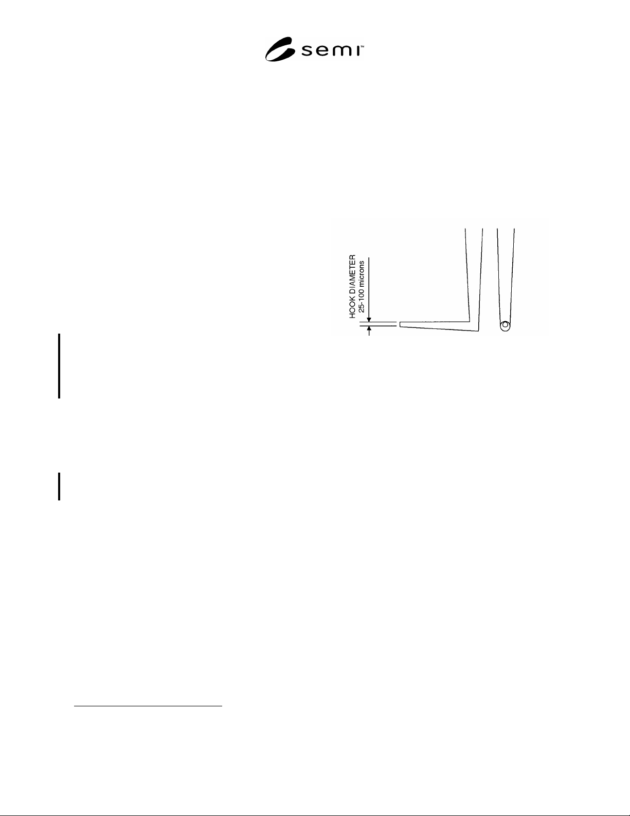
5.1.4 Hooks — Between 25–100 microns in diameter.
1 United States Military Standards, Available through the Naval
Publications and Forms Center, 5801 Tabor Avenue, Philadelphia,
PA 19120-5099, USA. Telephone: 215.697.3321
NOTE 1: Hook must be made of material strong enough to
break wire while testing but not with a small diameter so as to
cut through the wire.
Figure 1
Hook Diameter
5.1.5 Calibration of equipment must be simple enough
so that users can calibrate it easily. Instructions for
calibration should be described in equipment manual.
6 Sampling
6.1 Measure at least 30 points from at least 2 devices.
From each side of the devices, select the same number
of wires randomly.
7 Calibration and Standardization
7.1 Calibration Method
7.1.1 Calibration of equipment should be done using
official and traceable weights.
7.1.2 Display the weight and verify whether the results
are within the equipment’s accuracy.
7.1.3 Repeat the measurement using other weights to
verify repeatability and linearity of the calibration.
7.2 Interval of Calibration
7.2.1 Calibrate at regular intervals at least once a year.
7.2.2 Calibration must be able to be done just before
testing when necessary or specifically instructed.
1 SEMI G73-0997 © SEMI 1997, 2004
8 Procedure
8.1 Fix samples using a clamper or adhesive, so that
the sample will not float, without applying excessive
stress to the wire.
8.2 Set pull speed to 0.5 mm/sec while measuring.
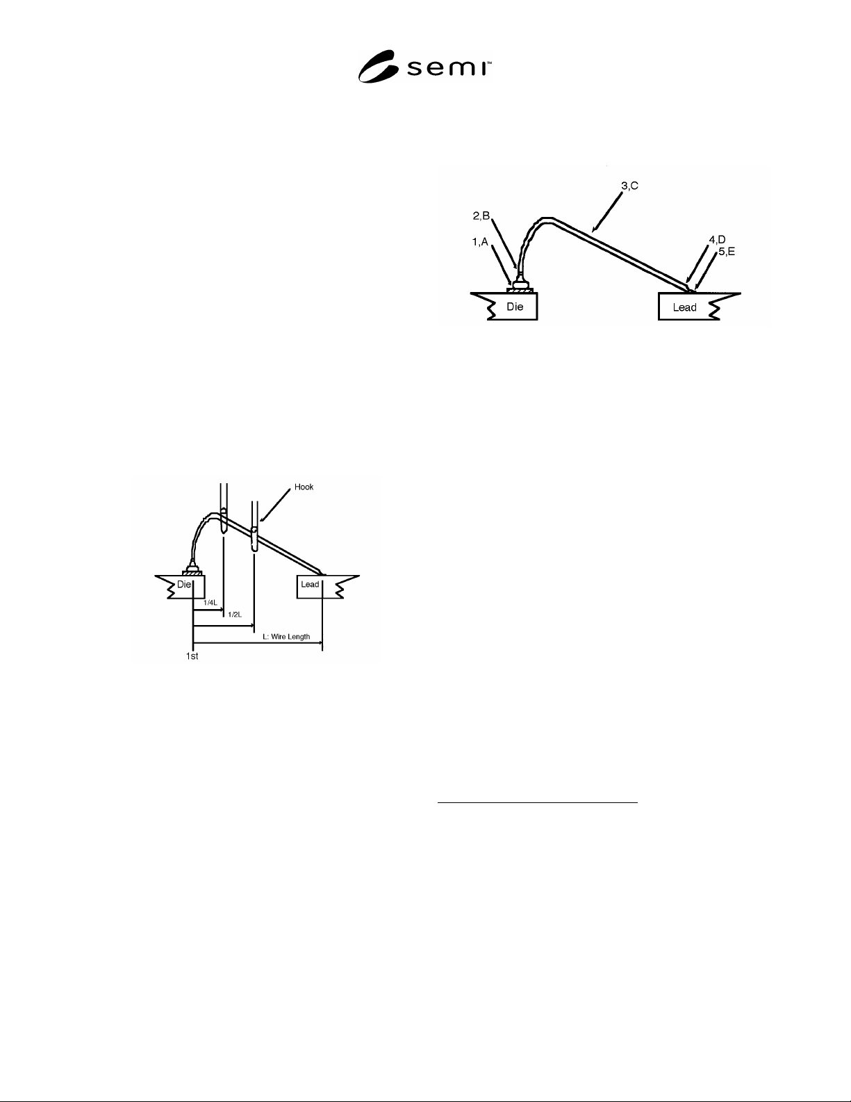
8.3 Insert the hook under the bonded wire between the
top of the first bonding and the center of the loop.
NOTE 2: Select hook position accordingly to package,
wiring condition, and wire diameter.
NOTE 3: Place the hook perpendicular to wiring direction if
there is no specific instruction.
NOTE 4: Do not measure damaged or deformed wire.
8.4 Pull the hook perpendicular to die/substrate.
8.5 Record the force that breaks the wire as the pull
strength.
8.6 Repeat the measurement on another wire.
NOTE 5: Do not change the position while testing the same
samples.
Figure 2
Hook Position
9 Report
9.1 Report of the pull test must contain the following
information.
9.2 Pull Strength
9.3 Breaking Mode — Choose the closest position
from Figure 3 below and represent the broken position
by number or alphabet in the figure.
9.3.1 Breaking Mode (Report in number or alphabet)
1,A: The first bond
2,B: The first bond neck
3,C: Loop
4,D: The second bond neck
5,E: The second bond
Figure 3
Breaking Mode
9.4 Hook Position
9.5 Rejection — Criterion of each semiconductor
manufacturer to each product. Refer to “Minimum
Strength” of the attached MIL-STD-883D.
10 Related Documents
10.1 SEAJ Document
2
SEAJ Technical Term Dictionary, 3rd Edition
10.2 JEITA Standard
3
JEITA ED4703 — In-Line Evaluation Methods and
Structural Analysis Methods for Semiconductor
Devices
10.3 IEC Standard
4
IEC 749 — Semiconductor Devices: Mechanical and
Climatic Test Methods
2 Semiconductor Equipment Association of Japan, 4F Grand Maison
Shinjuku Gyoen., 1-7-10 Shinjuku Shinjuku-ku, Tokyo 160-0022
Japan, 03(3353)7651 Fax 03(3353)7970,
http://www.seaj.or.jp/english/index.htm.
3 Electronic Industries Association of Japan, Available through:
Japan Electronics and Information Technology Industries
Association, 3rd Fl., Mitsui Sumitomo Kaijo Bldg. Annex 11, Kanda
Surugadai 3-chome, Chiyoda-ku, Tokyo 101-0062, Japan,
http://www.jeita.or.jp/eiaj/english/
4 International Electrotechnical Commission, 3 rue de Varembe, CH-
1211, Geneva 20, Switzerland, Phone: 41 22 919 02 11, Fax: 41 22
919 03 00, E-mail: IEC Central Office, http://www.iec.ch/
SEMI G73-0997 © SEMI 1997, 2004 2
APPENDIX 1
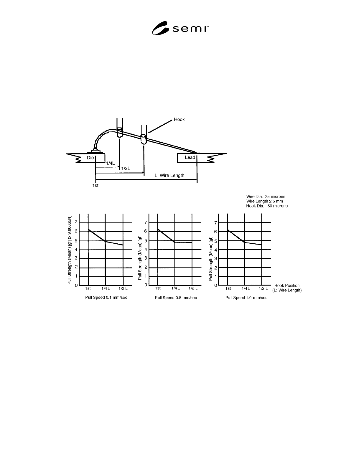
HOOK POSITION VS. PULL STRENGTH (DEPENDENCE ON PULL
SPEED)
NOTICE: The material in this appendix is an official part of SEMI G73 and was approved by full letter ballot
procedures.
A1-1
Figure A1-1
3 SEMI G73-0997 © SEMI 1997, 2004