semi合集-English.pdf - 第4732页
SEMI C3.24-03 01 © SEMI 1984 , 2001 2 50 mL high-density pol yethylene bottles Assorted Class A volume tric fla sks Ion chrom atograph Anion column which sepa rates: F - , Cl - , Br - , SO 4 -2 , PO 4 -3 4.2.2 Ion C hrom…
SEMI C3.24-0301 © SEMI 1984, 20011
SEMI C3.24-0301
SPECIFICATION FOR SULFUR HEXAFLUORIDE (SF
6
) IN CYLINDERS,
99.97% QUALITY
This specification was technically approved by the Global Gases Committee and is the direct responsibility of
the North American Gases Committee. Current edition approved by the North American Regional Standards
Committee on November 22, 2000. Initially available at www.semi.org January 2001; to be published March
2001. Originally published in 1984; previously published in 1995.
1 Description
1.1 Sulfur hexafluoride is colorless and odorless. It is
noncombustible and has a low toxicity. It is shipped as
a liquefied gas under its own vapor pressure.
2 Specifications
QUALITY: 99.97%
Impurities
Maximum Acceptable Level
(ppm) (See NOTE 1.)
Air 100
Carbon Tetrafluoride (CF
4
) 100
Hydrogen Fluoride (HF) 1
Water (H
2
O) (mol/mol) 8
TOTAL LISTED
IMPURITIES
209
NOTE 1: An analysis of significant figures has not been considered.
The number of significant figures will be based on analytical
accuracy and the precision of the provided procedure.
3 Physical Constants (for in formation only)
Metric Units US Units
Molecular weight 146.054 146.054
Boiling point at 1 atm -63.7°C -82.7°F
Density of gas at 20°C
(68°F) and 1 atm
6.162 kg/m
3
0.385 lb/ft
3
Specific gravity of gas at
21.1°C (70°F) and 1 atm
(air = 1)
5.114 5.114
Density of liquid at -50°C 1910 kg/m
3
119.2 lb/ft
3
4 Analytical Procedures (No tes 1, 2, and 3)
4.1 Air and Carbon Tetrafluoride — This procedure is
for the determination of air and carbon tetrafluoride
using a gas chromatograph with a thermal conductivity
detector.
4.1.1 Detection Limit — 1 ppm (mol/mol)
4.1.2 Instrument Parameters
4.1.2.1 Column: 2.4 m (8 ft) by 6.4 mm (1/4 in) OD,
5.1 mm (0.201 in) ID stainless steel tubing packed with
Porapak Q (80/100 mesh) or equivalent.
4.1.2.2 Carrier Flow: 30 mL/min helium.
4.1.2.3 Sample Volume: 1 mL.
4.1.2.4 Temperatures:
Detector 110°C
Column 70°C
4.1.3 Calibration Standards — 90–100 ppm
(mol/mol) carbon tetrafluoride, 90–110 ppm (mol/mol)
Air (O
2
/N
2
blend), balance helium.
4.1.4 Operating Procedure
4.1.4.1 Inject the calibration standard. Analyze the
standard using the conditions described above. Record
the retention times and peak areas.
4.1.4.2 Inject the sample to be tested in the same
manner as the calibration standard. Record the retention
times and peak areas.
4.1.4.3 Repeat 4.1.4.1.
4.1.4.4 Calculate the concentrations of air and carbon
tetrafluoride in the sample, using the formula below.
The result may not exceed the specification in Section 2
of this Standard.
Sample Peak Area
Standard Peak Area
×
Concentration
of Standard
=
Concentration
of Sample
4.2 Hydrogen Fluoride — This procedure is for the
determination of hydrogen fluoride by quantitative
collection in dilute sodium carbonate (NaHCO
3
) and
subsequent analysis by ion chromatography.
4.2.1 Detection Limit — 0.1 ppm for the method
Equipment Required:
500 mL Greenburgh impinger
50 mL Class A pipet
Type 316 stainless steel delivery system
5' Fluorocarbon tubing, 1/4 in OD by 0.03 in wall
Reagent Grade sodium bicarbonate
Deionized water
SEMI C3.24-0301 © SEMI 1984, 2001 2
50 mL high-density polyethylene bottles
Assorted Class A volumetric flasks
Ion chromatograph
Anion column which separates:
F
-
, Cl
-
, Br
-
, SO
4
-2
, PO
4
-3
4.2.2 Ion Chromatograph Parameters:
Instrument: Dionex 2000 (or equivalent)
Integrator: Dionex 4270 (or equivalent)
Column: HDIC AS4A (or equivalent)
Eluent: 0.001 M Na
2
CO
3
+ 0.001 M NaHCO
3
Flow Rate: 2 mL/minute
Pressure: 960 psia
Detector
Conductivity
Range:
3.0 microsiemens for less than 10 ppm
Sample: 100 microliters
4.2.3 Calibration — Calibrate the ion chromatograph
by dissolving a weighed amount of ammonium fluoride
(NH
4
F) in deionized water and sequentially diluting it
to a fluoride concentration of 0.1 ppmw in Class A
volumetric flasks and analyzing it as specified by the
instrument manufacturer.
4.2.4 Operating Procedure
4.2.4.1 Prepare a fresh solution of 1.7 mM sodium
bicarbonate in deionized water.
4.2.4.2 Pipet 200 mL of the solution into a 500 mL
Greenburgh impinger.
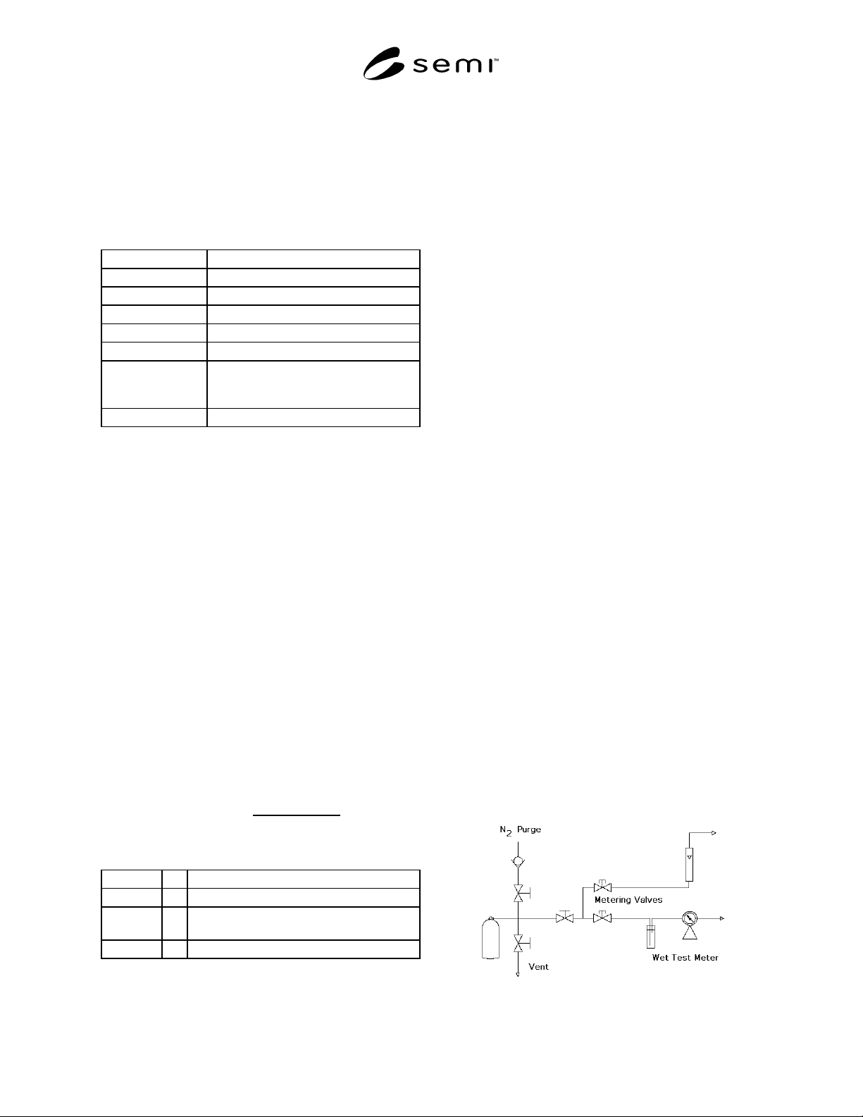
4.2.4.3 Bubble approximately 20 L of sulfur
hexafluoride (SF
6
) through the solution, using the
delivery system shown in Figure 1.
4.2.4.4 Analyze the solution as specified by the
instrument manufacturer.
4.2.4.5 Calculation — Calculate the concentration of
hydrogen fluoride (HF) using the following formula:
ppmv HFg =
(F
-
ppmw)×Vg
19.00×mg
Where:
F
-
ppm = Fluoride concentration in trapped solution.
Vg = Volume of collection solution (mL).
mg = Moles of SF
6
bubbled through the collecting
solution.
19.00 = Molecular weight of F
-
.
The result may not exceed the specification in Section 2
of this Standard.
4.3
Water — This procedure is for the determination
of trace moisture (water) in sulfur hexafluoride using a
continuous flowing electrolytic hygrometer. (See Notes
4, and 5.)
4.3.1
Detection Limit — 1.0 ppm (vol/vol) or -76°C
(-105°F).
4.3.2 Sample Pressure and Flow — Set in accordance
with instrument manufacturer’s instructions.
4.3.3 Operation Check — Check the instrument
periodically for correct operation. A gas containing a
known amount of moisture should be passed through
the instrument. Agreement between the hygrometer and
the standard should be within their relative accuracies.
4.3.4
Operating Procedure
4.3.4.1 Obtain a continuous flow samp le of sulfur
hexafluoride source, using a clean, electropolished or
passivated stainless steel line which has been purged
dry after exposure to ambient moisture. (See Note 5.)
4.3.4.2
After prepurging with a dry gas, allow the
sample gas to flow through the sampling system and
hygrometer until a stable reading is obtained. The
reading may not exceed the specification in Section 2 of
this Standard.
4.4
Notes
NOTE 1: Introduce the calibration standard as many times as
necessary to achieve the desired precision.
NOTE 2: All gases used in the analysis of the sample should
not contain more than 10% of the specified value of the
component of interest, unless otherwise stated.
NOTE 3: Observe proper safety procedures for handling and
disposing of sulfur hexafluoride (SF
6
).
NOTE 4: The sampling system and hygrometer must be
designed to operate at the sample pressure, or the sample
pressure must be reduced (by a regulator with a diaphragm of
stainless steel or other suitable material) to accommodate the
pressure restrictions of the hygrometer.
NOTE 5: A passivation procedure is described in Metals
Handbook, Eighth Edition, Volume 2, ASM International,
Metals Park, Ohio.
Figure 1

SEMI C3.24-0301 © SEMI 1984, 20013
NOTICE: These standards do not purport to address
safety issues, if any, associated with their use. It is the
responsibility of the user of these standards to establish
appropriate safety and health practices and determine
the applicability of regulatory limitations prior to use.
SEMI makes no warranties or representations as to the
suitability of the standards set forth herein for any
particular application. The determination of the
suitability of the standard is solely the responsibility of
the user. Users are cautioned to refer to manufacturer’s
instructions, product labels, product data sheets, and
other relevant literature respecting any materials or
equipment mentioned herein. These standards are
subject to change without notice.
The user’s attention is called to the possibility that
compliance with this standard may require use of
copyrighted material or of an invention covered by
patent rights. By publication of this standard, SEMI
takes no position respecting the validity of any patent
rights or copyrights asserted in connection with any
item mentioned in this standard. Users of this standard
are expressly advised that determination of any such
patent rights or copyrights, and the risk of infringement
of such rights, are entirely their own responsibility.
Copyright by SEMI® (Semiconductor Equipment and Materials
International), 3081 Zanker Road, San Jose, CA 95134. Reproduction o
f
the contents in whole or in part is forbidden without express written
consent of SEMI.