semi合集-English.pdf - 第6454页
SEMI G76-0299 © SEMI 1999 10 (3) Preparation Place for more than 1 hour in a managed en vironment of room temperature ± 2 ° C, ± 5% R.H. (4) Measuring Method Before Heating Measure the distance between the marks with…
SEMI G76-0299 © SEMI 1999 9
bridge is balanced, and C
0
is the electrostatic
capacity where εr = 1 calculated from the
main electrode area and sample thickness
according to the following formula):
t
r
C
6.3
2
0
=
(b) Dielectric Dissipation Factor
fCx
Gx
π
δ
2
tan =
100
S
GGx ×=
Where Gx is the sample conductance, G is
the conductance between m and d, S is the
resistance value between m and r, S/100 is
the resistance factor, f is the measuring
frequency, and π is pi.
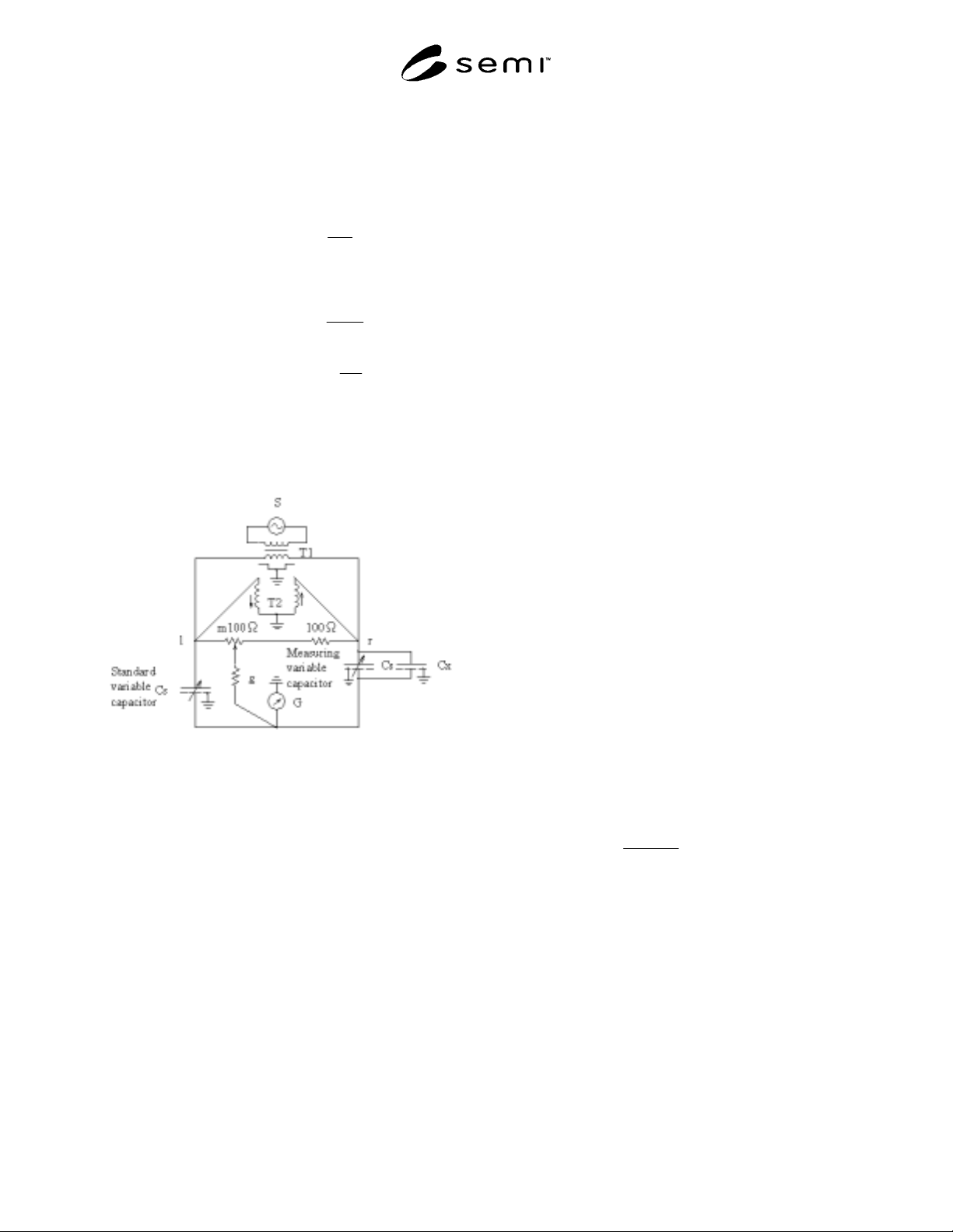
Figure 4
Measurement Circuit for Relative Permittivity and
Dielectric Dissipation Factor
8.7 Other Tests
8.7.1 Heat Resistance
(1) Equipment
(a) Solder Use Standard H60A or H63A
under JIS Z-3282.
(b) Solder Bath A vessel with a depth of
more than 50 mm to hold the solder at
between 200–300°C and can be adjusted
± 3°C.
(1) Material Using the TCP polyimide adhesive
tape as received from the vendor, laminate and
cure it according to the method described in
Section 8.2. Cut into 25 mm squares for
samples.
(2) Preparation Keep in 105 ± 5°C oven for 1
hour.
(3) Test After preparation, quickly place in 260
± 5°C solder bath and let float for 5
+ 1
-0
seconds.
Perform visual check for swelling.
8.7.2 Water Absorption Test
(1) Equipment
(a) Scale Use a scale that can measure in
1 mg units.
(b) Vessel Use a vessel in which the
samples can be totally immersed.
(c) Dessicator Use a dessicator which
allows samples heated to 80°C to cool
off.
(1) Material Using the TCP polyimide
adhesive tape as received from the vendor,
laminate and cure it according to the method
described in Section 8.2. In addition, remove
all copper foil by etching, and dry for 30
minutes at 80 ± 5°C. Cool in the dessicator,
and use samples cut into length 500 ± 5 mm,
and width 20 ± 1 mm. Depending on the
shape of the vessel to be used for
immersion, it is feasible to several pieces of
a suitable length.
(2) Test Weigh the sample in increments of 1
mg. Place sample in 23 ± 2°C distilled water.
After 24 ± 1 hours, wipe off water and
measure sample again in increments of 1 mg.
(3) Calculation Use the following formula:
(%)100
2
12
×
−
W
WW
Where W
1
and W
2
are the weight before and
after immersion respectively.
8.7.3 Heat Shrinkage Use the standard value of the
base film and the various values for measuring
conditions.
(1) Equipment Use a measuring device with
optical equipment which can read with at
least 5/100,000 (0.005%) precision.
(2) Material Mark three places along the
width on a sample with size larger than 50
mm square.

SEMI G76-0299 © SEMI 1999 10
(3) Preparation Place for more than 1 hour in
a managed environment of room
temperature ± 2°C, ± 5% R.H.
(4) Measuring Method Before Heating
Measure the distance between the marks
with the equipment (1) on a sample that has
been prepared according to (3) above.
(5) Heating Keep the samples in an oven at
200 ± 3°C for more than an hour, making
sure that it is not effected from the outside.
(6) After-Processing Leave sample for more
than 1 hour in the conditions described in (3)
above.
(7) Measuring Method After Heating Use the
same method as (4) above.
(8) Calculation Use the following formula,
where L
1
is the dimension from (4), and L
2
is the dimension from (7):
(%)100
1
21
×
−
L
LL
8.7.4 Coefficient of Thermal Expansion Use the
standard value of the base film and the various values
for measuring conditions.
(1) Equipment Use TMA equipment.
(2) Material Prepare sample with width of 3
mm and length of more than 15 mm.
(3) Preparation To remove the effects of
thermal shrinkage and moisture, heat at
more than 300°C for 30 minutes.
(4) Measuring Method With a sample that has
been prepared according to (3) above,
measure the stretching in the sample on a
TMA, in the range between room
temperature and 300°C, raising the
temperature at less than 20°C/min.
(5) Calculation Use the following formula,
reading a gradient from an arbitrary scope,
within the area between room temperature
and 200°C (i.e., 50−200°C, 100−200°C):
)(
6
100
)
01
(
0
01
ppm
TTL
LL
×
−
−
Where T
0
and T
1
are the temperatures in the
area for Linear Expansion, L
0
is the length
of the sample at T
0
(°C) and L
1
is the length
of the sample at T
1
(°C).
8.7.5 Tensile Strength, Elongation Use the standard
value of the base film and the various values for
measuring conditions.
(1) Equipment Use a pull strength meter and
recorder.
(2) Material Use samples with a width of
more than 10 mm and length of
approximately 200 mm. The samples should
be 3 pieces taken from the beginning,
middle and end of the roll.
(3) Measuring Method After measuring the
width of the sample, fix it in the pull
strength meter. Use a clamping distance of
approximately 100 mm to test pull strength.
Measure the pull load and stretch at point of
breakage.
(4) Calculation After measuring the pull
strength and elasticity of each sample,
calculate the average of each.
8.7.6 Flammability
(1) Equipment
(a) Sample box or draft chamber which can
maintain calm conditions.
(b) Test stand and clamp.
(c) Bunsen burner with pipe length of
approximately 100 mm, aperture
diameter of 9.5 ± 0.5 mm, using methane
gas or natural gas with a heat generation
volume of approximately 37 MJ/m
3
.
(d) Stop-watch or timer.
(e) Sheet of absorbent cotton 50 mm square
with a maximum natural thickness of 6.4
mm.
(f) A dessicator with dehydrated hydrated
calcium.
(g) A test oven which can maintain a
temperature of 23 ± 2°C and R.H. of 50
± 5%.
(h) A test oven which can maintain a
temperature of 70 ± 1°C.
(i) A pole with a diameter of 13 ± 5 mm.
(2) Material Using the TCP polyimide
adhesive tape as received from the vendor,
laminate and cure it according to the method
described in Section 8.2. In addition, remove
all copper foil by etching, and dry for 30
minutes at 80 ± 5°C. As shown in Figure 5,

SEMI G76-0299 © SEMI 1999 11
use a sample with a length of 200 mm and
width of 50 mm, and mark a line in the TD
direction at 125 mm from the bottom. With
the mark line facing outward, wrap the
sample around the pole and hold in place
with tape within 76 mm about the mark line.
Remove the pole to leave a tube of the
sample. Prepare 2 groups of 5 pieces each.
(3) Preparation Leave one group of samples
in normal condition for 48 hours. Heat the
other group at 70 ± 1°C for 168 hours, place
them in the dessicator with dehydrated
hydrated calcium and keep for more than 4
hours at 23°C.
(4) Test Perform the following test on the
two groups of samples prepared as described
in Section 8.7.6, (3) above:
(a) As shown in Figure 6, fix the sample
perpendicular in the ring stand with the
clamps, with the tip of the burner 10
mm below the edge of the sample, and
the absorbent cotton placed horizontal
at 300 mm below the edge.
(b) Light the burner away from the sample,
and adjust to a blue flame of 20 ± 1 mm
long. Keeping the length at 20 ± 1 mm,
make sure there is no yellow flame at
the tip.
(c) Apply the flame to the center of the edge
of the sample for 3 seconds. Then
remove the flame to more than 150 mm
away, and record the flaming time.
When the flame burns out, apply the
flame to the edge of the sample for 3
seconds and pull away again. Measure
the flaming time it takes to reach the
clamp as well as the glowing time.
Also, record whether the absorbent
cotton has caught fire or not. When
there are molten particles or burning
material drippings from the sample, it is
acceptable to tip the burner 45° and
move the flame from the bottom edge to
avoid material dripping on the burner.
In this case, the distance from the
bottom edge of the sample to the tip of
the burner should still be 10 mm.
(5) Items to Record
(a) Flaming time after the first and second
application.
(b) Sum of flaming and glowing time after
second application.
(c) Flaming or glowing up to the clamp or mark
line.
(d) Existence of dripping material which caused
the absorbent cotton to burn.
8.8 Test for External Defects
8.8.1 MD Curl
(1) Equipment Use a scale that measures at
least 1 mm increments.
(2) Material Cut a section of more than 30
cm, but less than 100 cm in length of TCP
polyimide adhesive tape as received.
(3) Measurement As shown in Figure 7,
remove the cover film, place on a flat surface
for more than 12 hours and measure the
highest point on the tape from the flat surface
in the MD direction.
8.8.2 TD Curl
(1) Equipment
(a) A scale that measures at least 1 mm
increments.
(b) A square block with a base with a length
of more than 15 cm and width of 2 cm,
and a weight of more than 500 g.
(2) Material Cut a section of more than 15
cm, but less than 30 cm in length of TCP
polyimide adhesive tape as received.
(3) Measurement
(a) Remove the cover film and place on a flat
surface for more than 12 hours.
(b) Use the block to hold down the sample
tape on the edge without adhesive. The
space held down should be more than 2
mm in from the edge, but before the
adhesive material.
(c) As shown in Figure 8, on the opposite side
of the tape for the block, measure the
highest point from the flat surface.
8.8.3 Wakame
(1) Equipment Use a scale that measures at
least 1 mm increments.
(2) Material Cut a section of more than 30
cm, but less than 100 cm in length of TCP
polyimide adhesive tape as received.