semi合集-English.pdf - 第6332页
5 SEMI G65-96 © SEMI 1996, 2004 Figure 7 Die Core Detail 8.3 Micrometer 8.4 Microsc ope — 75× used to inspect lead surface characteristics. 8.5 Protr a ctor — 10× and accuracy 0.1° used to m easure the leadform spring ba…
SEMI G65-96 © SEMI 1996, 2004 4
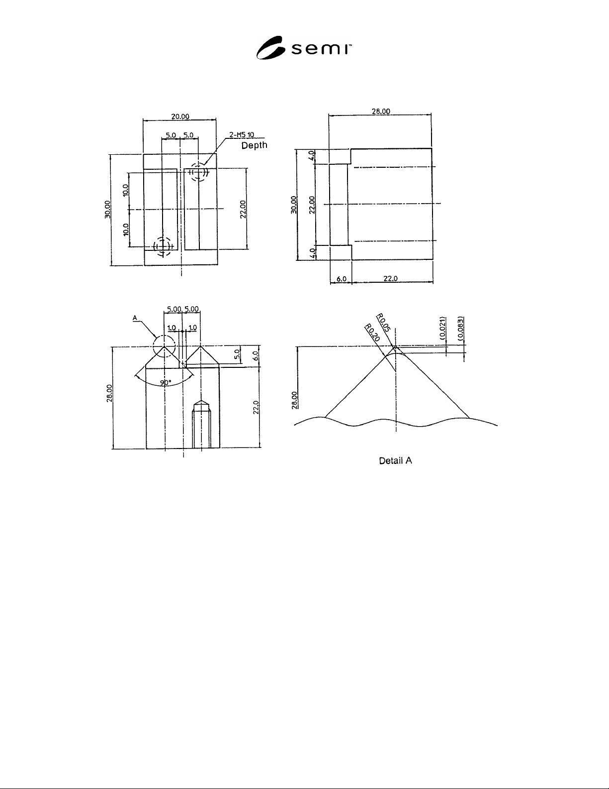
Figure 6
Punch Core Detail
5 SEMI G65-96 © SEMI 1996, 2004
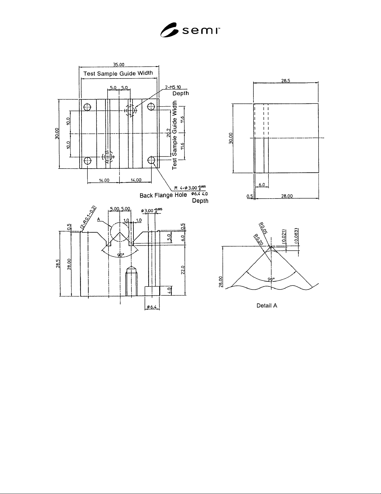
Figure 7
Die Core Detail
8.3 Micrometer
8.4 Microscope — 75× used to inspect lead surface characteristics.
8.5 Protractor — 10× and accuracy 0.1° used to measure the leadform spring back.
8.6 Projector — 10×.
9 Sampling Plan
9.1 The sampling plan shall be agreed between user and supplier. It is suggested that a minimum of five (5) samples
(2 leads per sample) of 0.3 mm width on 0.65 mm pitch, be used for these tests.
NOTE 3: If the leadframe is four-sided, take samples from both orthogonal directions.
SEMI G65-96 © SEMI 1996, 2004 6
10 Sample Preparation
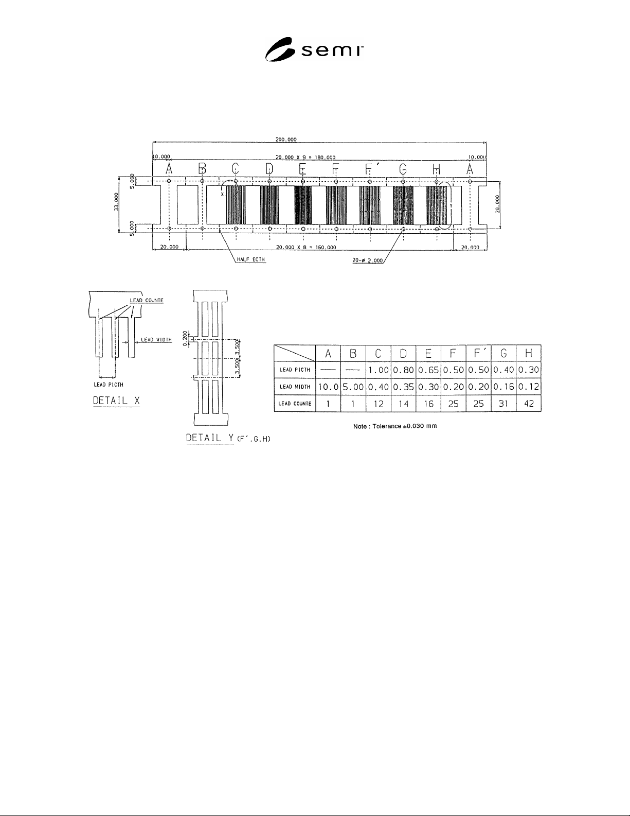
10.1 The samples are prepared by etching a leadframe pattern into a blank piece of the leadframe material using a
standard mask. An example of the recommended configuration is shown in Figure 8.
Figure 8
Standard Sample Configuration
10.2 Measure the sample thickness at three (3) points on the siderail using micrometer.
11 Setup and Procedure
11.1 Setup
11.1.1 Warm up and calibrate the tensile tester according to the operation manual.
11.1.2 Set the “W” forming tool in the tensile tester.
11.1.3 Set the tensile tester in the push mode and adjust the force to 9800N.
11.2 Procedure
11.2.1 Place the sample on the lower section of the “W” forming tool.
11.2.2 Lower the upper section of the “W” forming tool at the speed of 1 to 5 mm/min.
11.2.3 Raise up the upper section of the “W” forming tool and remove the sample carefully.
11.2.4 Repeat the test for the other samples.
11.3 Measurement
11.3.1 Remove the leads from the bent sample by cutting at the cutting position.