semi合集-English.pdf - 第4552页
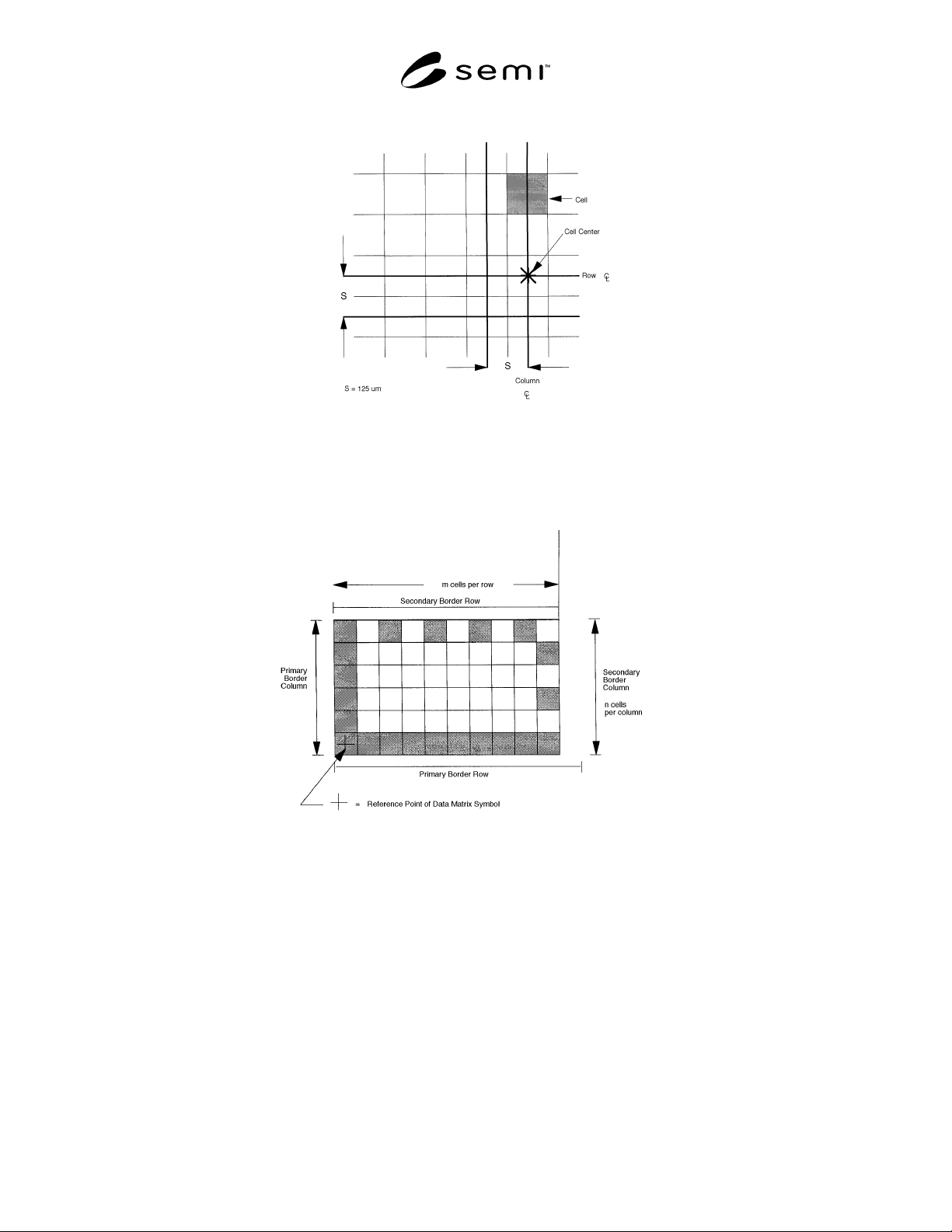
SEMI D26-1000 © SEM I 2000 11 Figure 8 Data Matrix Cell Dimensions Figure 9 Border Rows and Columns
SEMI D26-1000 © SEMI 2000 10
9.5 Content of the Data Matrix Co de Symbol
9.5.1 Each rectangular matrix code symbol shall
contain between 46 message characters (for 16 rows ×
36 columns) and 72 message characters (for 16 rows ×
48 columns), encoded in accordance with AIM
International Symbology Specification – Data Matrix.
9.5.2 The message characters may include any of
those designated as “mostly upper case” Annex K of
AIM International Symbology Specification – Data
Matrix. 8-bit characters may also be encoded with
reduced field capacity. The first 20 characters shall
contain two elements:
a. a vendor-assigned 15-character mask identification
code, followed
by
b. a 1-character field concatenation symbol (+) and 2-
character field ID (per ANSI MH 10.8)
9.5.3 The next 26 message characters shall contain
two elements:
a. a customer-assigned 13-character part #, followed
by
b. a 1-character field concatenation symbol (+)
followed by a 2-character field ID and
c. a 12-character customer-assigned part revision
number.
9.5.4 The remaining message characters, if any, shall
contain information as agreed between the vendor and
the user. This may require field identifiers and field
concatenation.
9.5.4.1 Field identifiers listed in ANSI MH 10.8.2
include:
a. Customer part number revision: 2P
b. Customer specification number: 20P
c. Customer specification revision: 21P
d. Customer drawing number: 12P
e. Customer drawing number revision: 22P
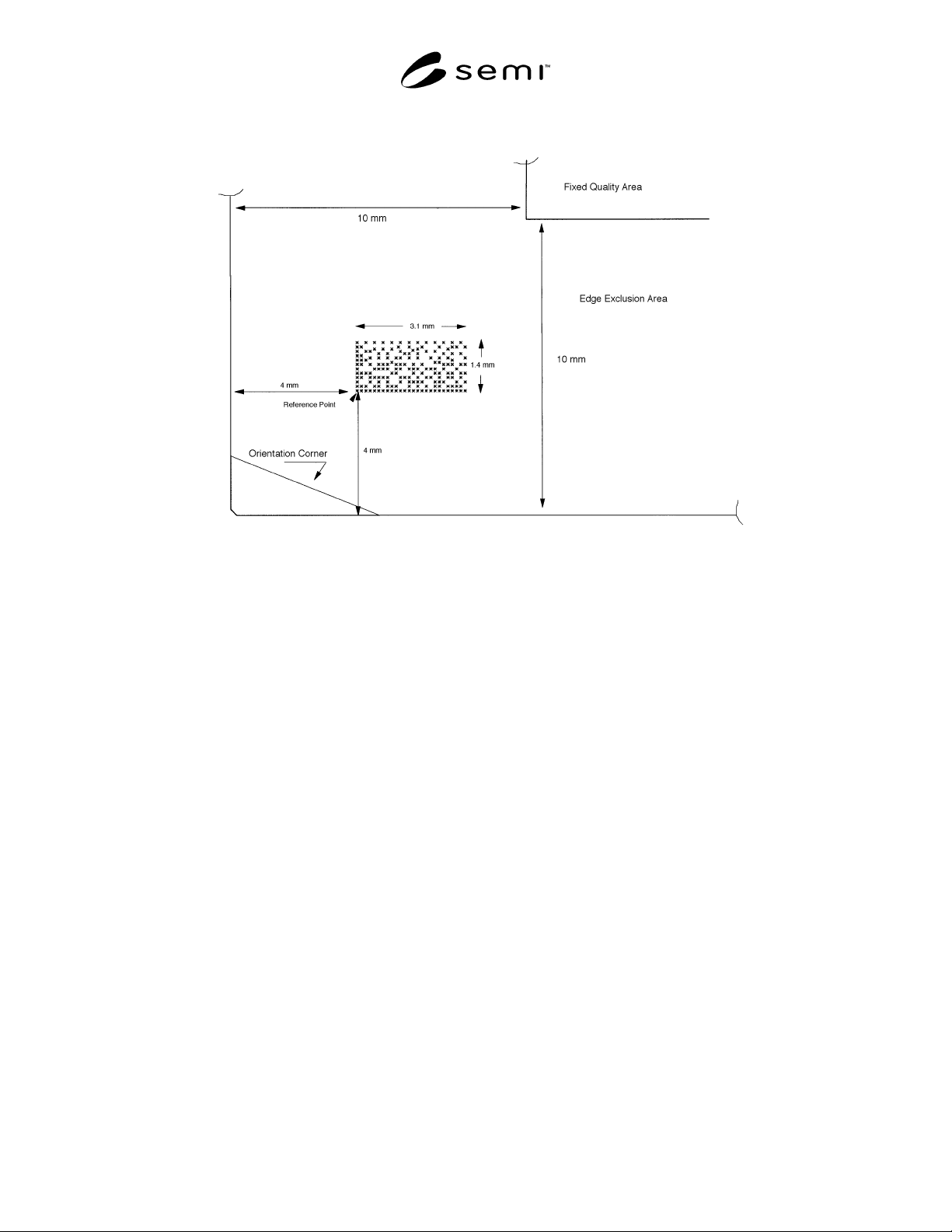
9.5.5 Location of the Data Matrix Code Symbol
9.5.5.1 With the substrate positioned front surface up
and with the orientation corner toward the operator and
to the operator’s left, the reference point of the data
matrix code symbol shall be placed toward the
orientation corner and
8 ± 1 mm from the substrate’s y-edge; this provides
clearance for corner cuts or other elements adjacent
to the corner, and
3 ± 1 mm from the substrate’s x-edge; this
approximately centers the field between the x-edge
and the FQA boundary.
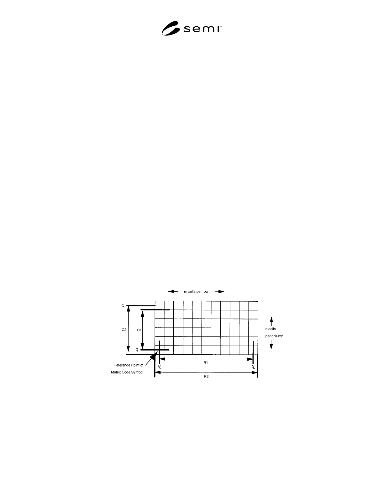
Figure 7
Data Matrix Field
SEMI D26-1000 © SEMI 200011
Figure 8
Data Matrix Cell Dimensions
Figure 9
Border Rows and Columns
SEMI D26-1000 © SEMI 2000 12
Figure 10
Data Matrix Code Field in Edge Exclusion Area
NOTICE: SEMI makes no warranties or representations as to the suitability of the standards set forth herein for any
particular application. The determination of the suitability of the standard is solely the responsibility of the user.
Users are cautioned to refer to manufacturer’s instructions, product labels, product data sheets, and other relevant
literature respecting any materials mentioned herein. These standards are subject to change without notice.
The user’s attention is called to the possibility that compliance with this standard may require use of copyrighted
material or of an invention covered by patent rights. By publication of this standard, SEMI takes no position
respecting the validity of any patent rights or copyrights asserted in connection with any item mentioned in this
standard. Users of this standard are expressly advised that determination of any such patent rights or copyrights, and
the risk of infringement of such rights, are entirely their own responsibility.
Copyright by SEMI® (Semiconductor Equipment and Materials
International), 3081 Zanker Road, San Jose, CA 95134. Reproduction o
f
the contents in whole or in part is forbidden without express written
consent of SEMI.