semi合集-English.pdf - 第2981页
SEMI E120-0705 © SEMI 2003, 2005 17 10 Compliance 10.1 This section defines requirements for compliance to this specification. 10.1.1 The term “CEM class” refers generally to any one of the classes defined by this specif…
SEMI E120-0705 © SEMI 2003, 2005 16
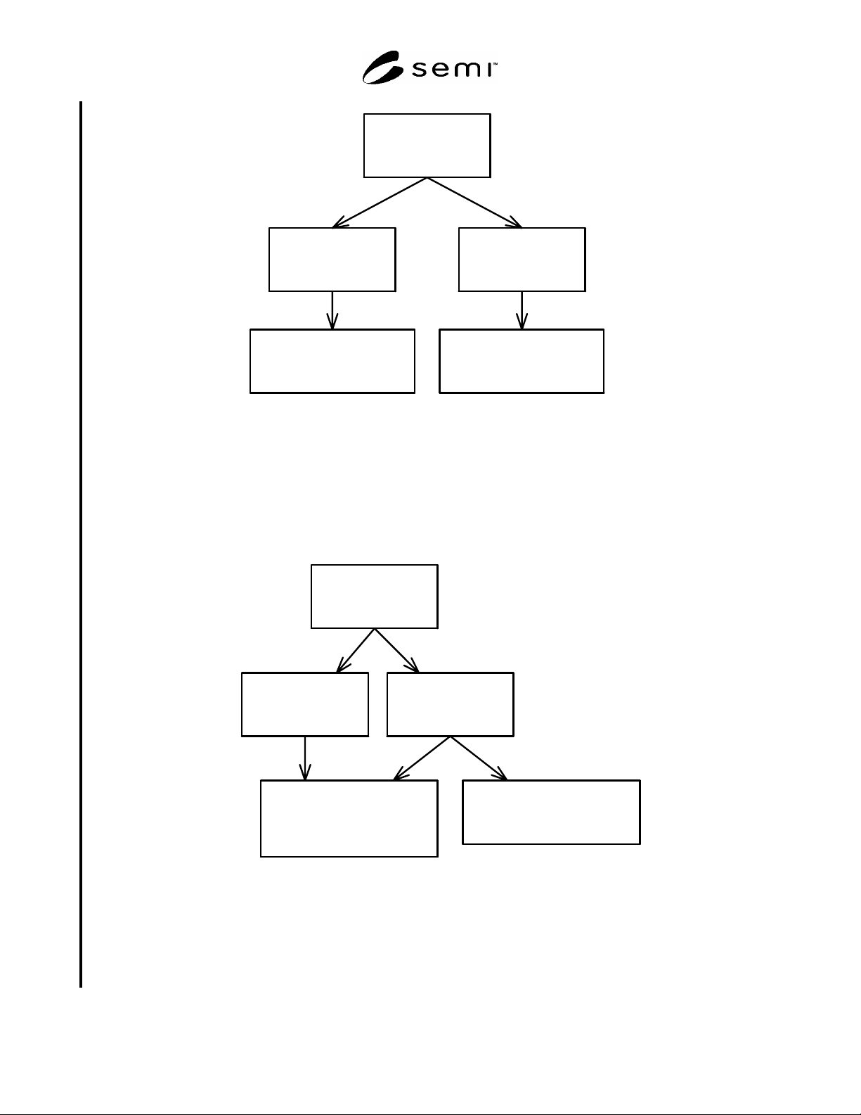
Object5 (Equipment)
name=Track
Locator=Track
Object6 (Subsystem)
name=Port-1
Locator=Track/Port-1
Object8 (Subsystem)
name=Power
Locator=Track/Port-1/Power
Object7 (Subsystem)
name=Port-2
Locator=Track/Port-2
Object9 (Subsystem)
name=Power
Locator=Track/Port-2/Power
Figure 14
Example: Equipment Hierarchy
9.2.2 In the case where an object is shared, there may be more than one Locator that will resolve to that object. The
block diagram in Figure 15 gives an example of the Locators that might result. Notice that Object8 is shared by
Object6 and Object7. This means that it can be referenced by two different but equally valid Locator values as
shown in the diagram. For Nameable instances with more than one possible Locator value, any valid Locator
construct will resolve to that object.
Object5 (Equipment)
name=Track
Locator=Track
Object6 (Subsystem)
name=Port-1
Locator=Track/Port-1
Object8 (Subsystem)
name=Power-1
Locator=Track/Port-1/Power-1
=Track/Port-2/Power-1
Object7 (Subsystem)
name=Port-2
Locator=Track/Port-2
Object9 (Subsystem)
name=Power-2
Locator=Track/Port-2/Power-2
Figure 15
Example: Equipment Hierarchy With Shared Object
9.2.3 Note that the Locator value is valuable as a reference to a Nameable. However, that value is not available
from the Nameable as an attribute. The Locator can be built independently and used when only the names are
known or when the position in the hierarchy is more important than the identity of the equipment component being
referenced.
SEMI E120-0705 © SEMI 2003, 2005 17
10 Compliance
10.1 This section defines requirements for compliance to this specification.
10.1.1 The term “CEM class” refers generally to any one of the classes defined by this specification. The term
“equipment component” refers generally to any part of the equipment that fits the definition of any subclass of
EquipmentElement (including Equipment, Module, Subsystem, and IODevice).
10.1.2 Compliance to this specification requires
1. Satisfaction of all requirements listed in Table 12, and
2. Satisfaction of all requirements for each CEM class that has been implemented (as reflected in the
corresponding row of Table 13).
10.1.3 The tables below each contain columns labeled “Implemented” and “CEM Compliant”. Each row represents
a requirement (or group of requirements).
10.1.4 The “Implemented” column communicates an assertion that the equipment has provided the function or
capability that corresponds to the intent of that requirement. This assertion is not testable. However, in order to be
“CEM Compliant”, the “Implemented” column would logically be set to “yes”.
10.1.5 A row/requirement is considered to be “CEM Compliant” when all defined aspects of that requirement have
been satisfied. Therefore, an implementation that is compliant to CEM would have:
All rows of Table 12 marked “yes” for both “Implemented” and “CEM Compliant”,
The “Equipment” row of Table 13 would be marked “yes” for both “Implemented” and “CEM Compliant”, and
Any other rows of Table 13 that are marked “yes” for “Implemented” would also be marked “yes” for CEM
Compliant”.
10.2 General CEM Compliance Requirements
10.2.1 There are five general CEM compliance requirements. They are listed in Table 12.
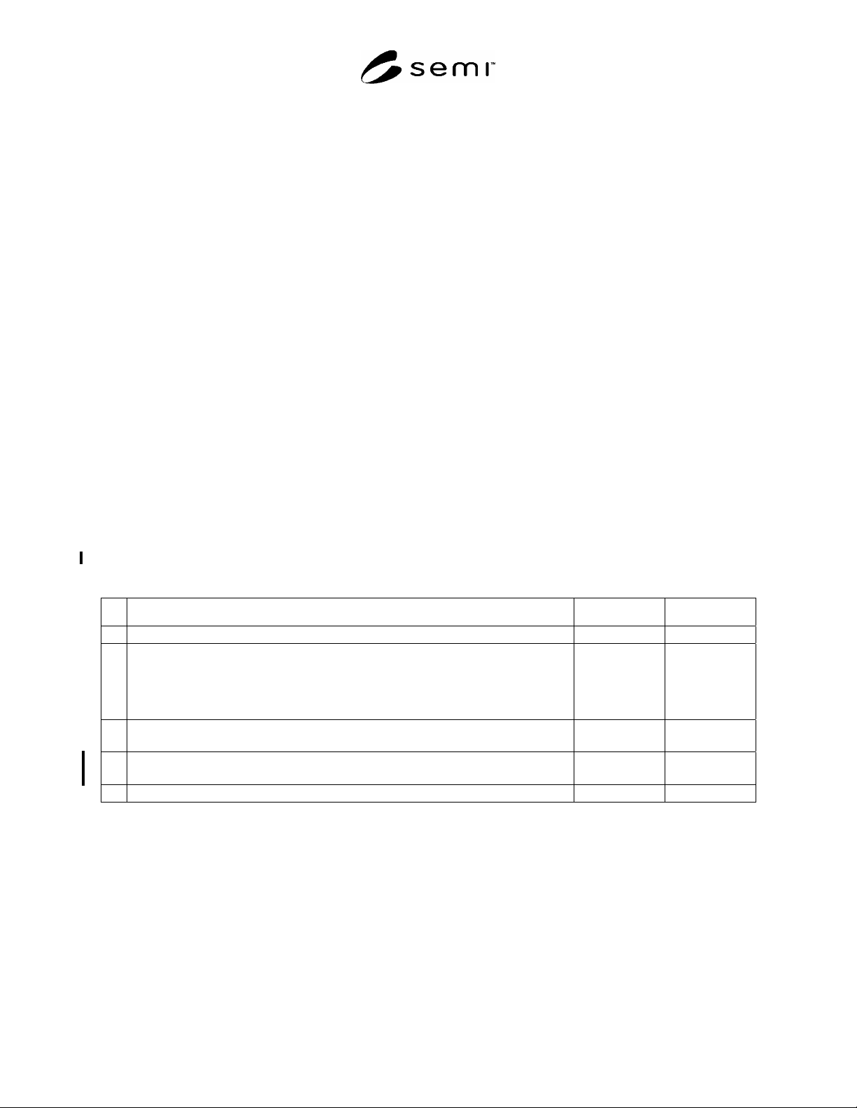
Table 12 General CEM Requirement Compliance Table
# CEM Requirement Implemented CEM Compliant
1 An Equipment instance shall be defined using the CEM Equipment class Yes No Yes No
2
When other equipment component instances are defined, they shall meet all
requirements for the corresponding CEM classes (see Table 13 and §8). Please note
that this specification does not require that all CEM classes be used in each equipment
implementation. Instead, it requires that all requirements for a class be met whenever
it is used.
Yes No Yes No
3 All object definitions that have been based on CEM classes shall be made available
electronically to the factory host.
Yes No Yes No
4
If the equipment provides a positional reference for an equipment component, the
Locator form as defined in §9 shall be used.
Yes No Yes No
5 Association Navigability shall be supported as defined in ¶6.2.7. Yes No Yes No
10.3 Specific Compliance Requirements
10.3.1 Table 13 lists each concrete class and references the section where requirements are defined for that class.
The requirements are primarily defined by the UML diagram and table of attributes in the referenced section. The
text of the section serves to clarify the requirements and add detail where appropriate.
10.3.2 On the UML diagram, note the associations and their cardinality and role specifications. Associations
(including aggregations) constitute requirements on a given class if navigable to the target class. (See ¶6.2.7 for an
explanation about Navigability and related requirements). For a navigable association, object(s) of the target class
are required. When the cardinality of the target class of the association may be zero, the association and target class
may be omitted as appropriate.
SEMI E120-0705 © SEMI 2003, 2005 18
10.3.3 In Table 13, the first column represents a CEM concrete class. “CEM Compliance” in this table indicates (1)
that at least one instance of that class exists and (2) that all instances of that class meet all requirements for the class.
10.3.4 The “Class/Superclass Definition” column gives a section number reference to each class in the inheritance
hierarchy for the concrete class in that row. The requirements for all classes in the inheritance hierarchy apply for
this concrete class.
10.3.5 The “Navigable Via Association” column lists the section number for the definition of each class that may be
associated with the concrete class in that row. When such an association exists, there must be a CEM Compliant
instance of that associated class. If the cardinality of the association may be zero, then the existence of the
association is dependent on the equipment structure.
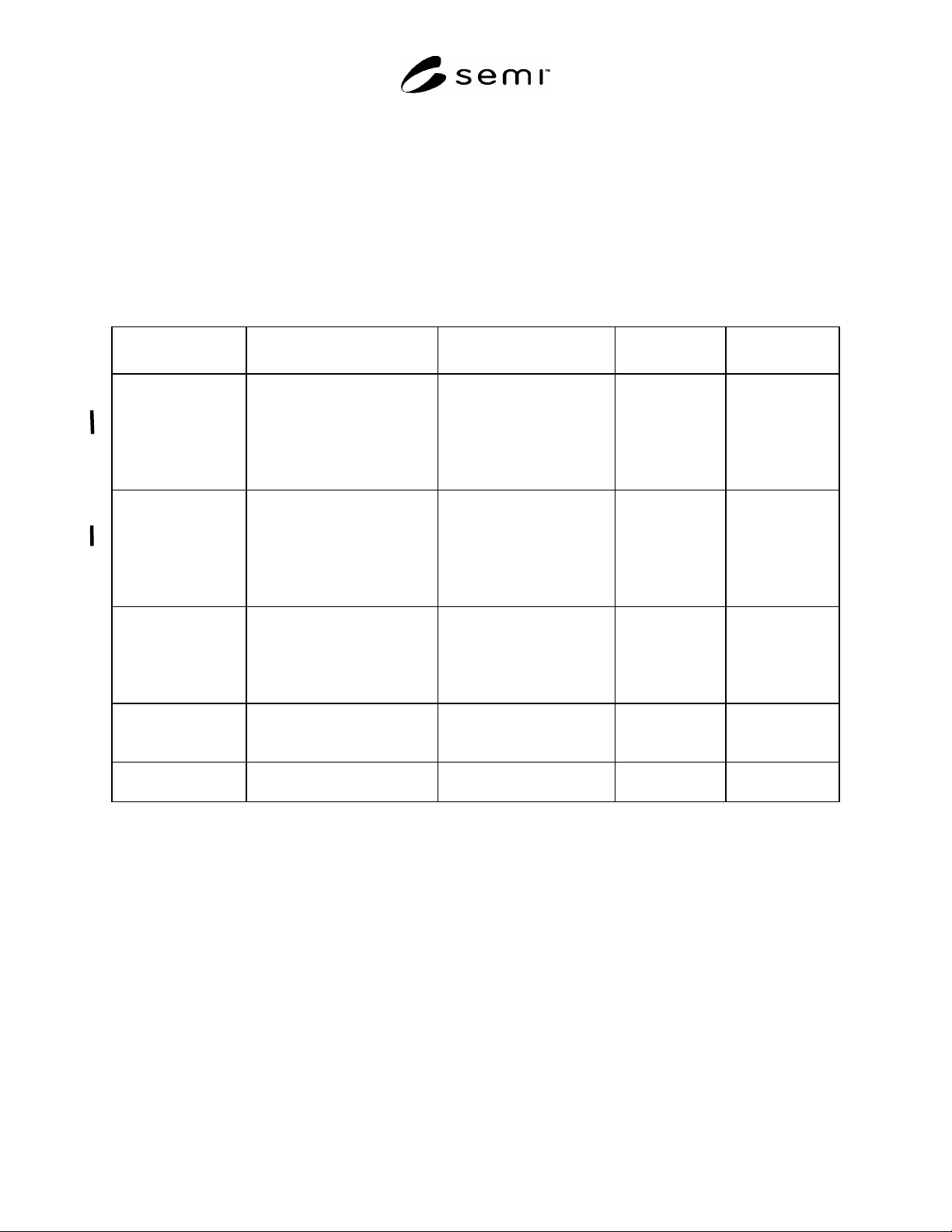
Table 13 CEM Class Compliance Table
CEM Class
Requirement
Class/Superclass
Definition
Navigable Via Association Implemented CEM Compliant
Equipment 8.5.3.1 Nameable
8.5.3.2 EquipmentElement
8.5.3.3 ExecutionElement
8.5.4.1 Equipment
8.5.3.4 Extension
8.5.4.2 Module
8.5.4.3 Subsystem
8.5.4.4 IODevice
8.5.4.5 MaterialLocation
8.5.4.6 SoftwareModule
Yes No Yes No
Module 8.5.3.1 Nameable
8.5.3.2 EquipmentElement
8.5.3.3 ExecutionElement
8.5.4.2 Module
8.5.3.4 Extension
8.5.4.2 Module
8.5.4.3 Subsystem
8.5.4.4 IODevice
8.5.4.5 MaterialLocation
8.5.4.6 SoftwareModule
Yes No Yes No
Subsystem 8.5.3.1 Nameable
8.5.3.2 EquipmentElement
8.5.4.3 Subsystem
8.5.3.4 Extension
8.5.4.3 Subsystem
8.5.4.4 IODevice
8.5.4.5 MaterialLocation
8.5.4.6 SoftwareModule
Yes No Yes No
IODevice 8.5.3.1 Nameable
8.5.3.2 EquipmentElement
8.5.4.4 IODevice
8.5.3.4 Extension
8.5.4.6 SoftwareModule
Yes No Yes No
MaterialLocation 8.5.3.1 Nameable
8.5.4.5 MaterialLocation
8.5.3.4 Extension Yes No Yes No
10.4 Compliance Verification Approach
10.4.1 Verification of compliance to SEMI E120 may be accomplished by comparing the objects and their
attributes that are reported from the equipment with their class definitions from CEM and with the other
requirements listed in this Table 12.
10.4.2 Electronic verification requires that all CEM related objects be collected directly from the equipment along
with all their attributes. The method for collection will vary depending on the type of electronic communication
available. Since the CEM classes and their attributes are static, the method and time of collection shall not affect the
verification outcome.
10.4.3 Once the objects are collected, the set is checked electronically against the requirements defined in Table 12
and Table 13 above. The process will ensure that the names of all classes and attributes are correct, that any
required objects exist and that each instance provides all defined attributes and appropriate associations.