semi合集-English.pdf - 第120页
SEMI E15-0698 E2 © SEMI 1990, 2003 5 Figure 4 Wafer and Casse tte Orientat ion, Wafers Horizontal Figure 5 Wafer and Casset te Orientatio n, Wafers Vertica l 8 Related Documents 8.1 SEM I Docume nts SEMI E47 — Specificat…
SEMI E15-0698
E2
© SEMI 1990, 2003 4
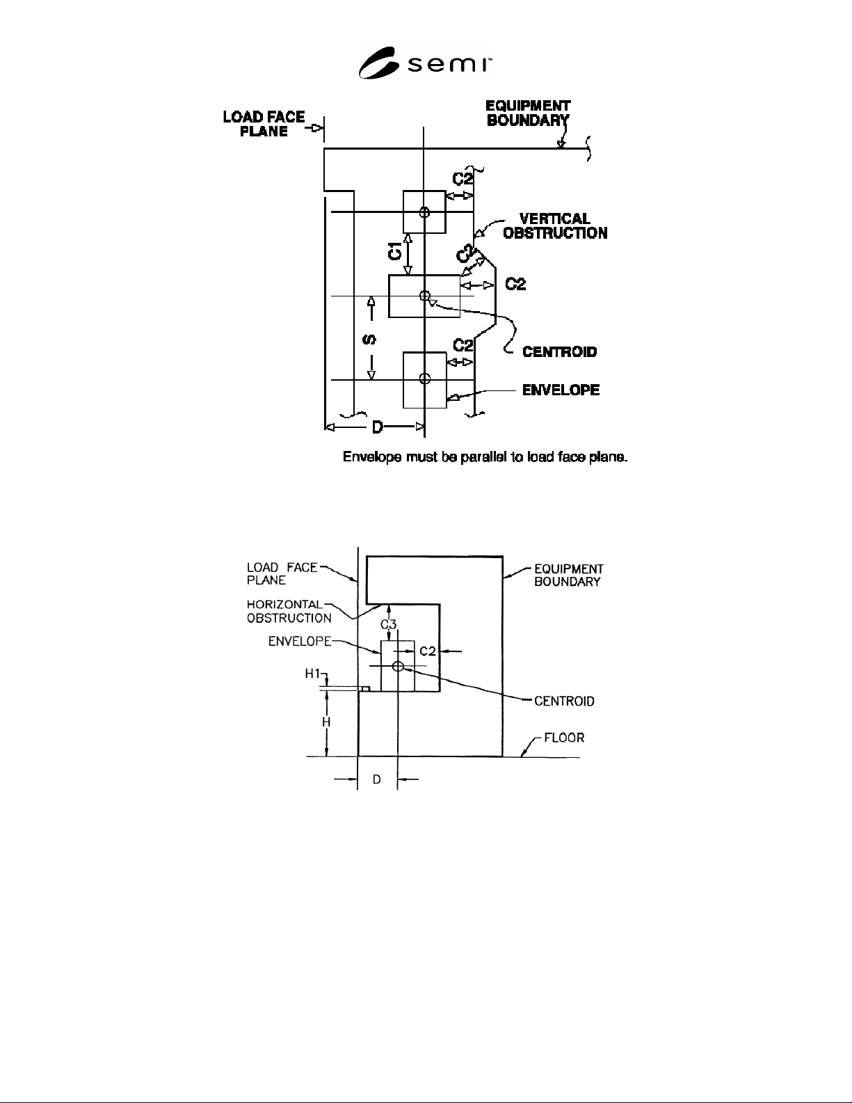
Figure 2
Load Port Requirements, Plan View
Figure 3
Load Port Requirements, Elevation View
SEMI E15-0698
E2
© SEMI 1990, 2003 5
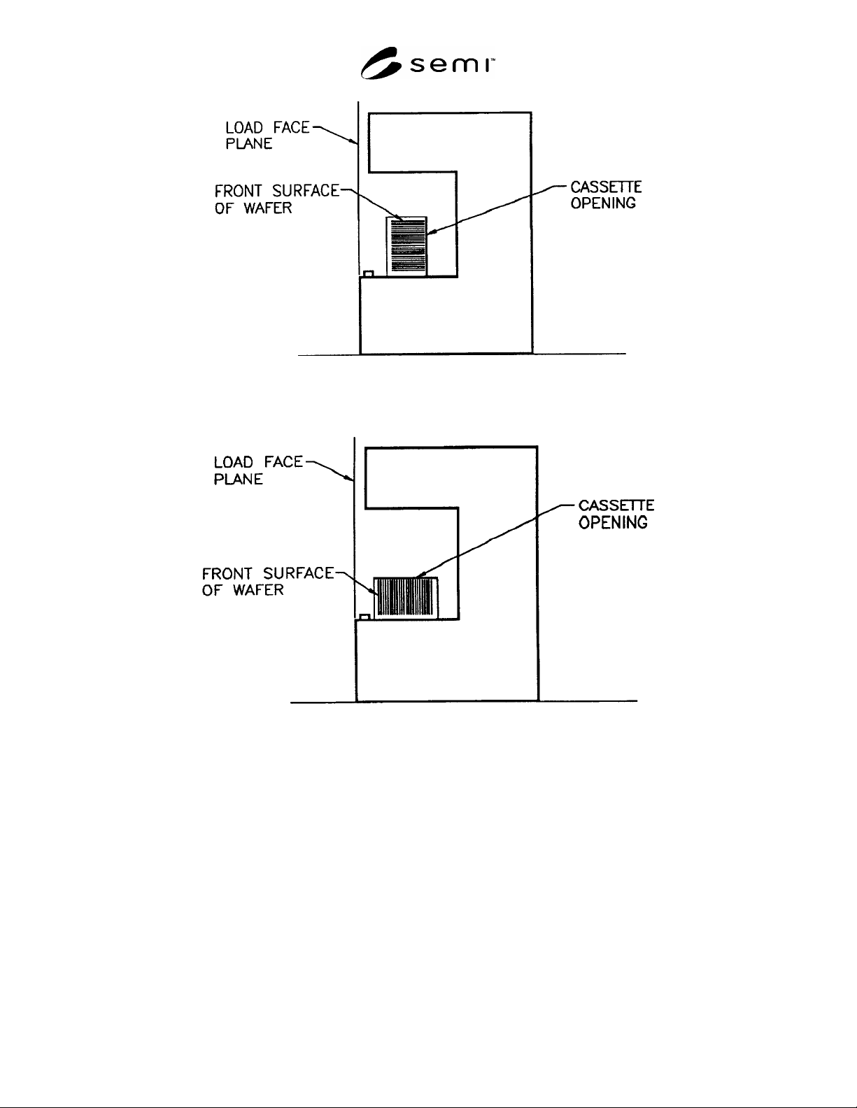
Figure 4
Wafer and Cassette Orientation, Wafers Horizontal
Figure 5
Wafer and Cassette Orientation, Wafers Vertical
8 Related Documents
8.1 SEMI Documents
SEMI E47 — Specification for 150 mm/200 mm Pod Handles
SEMI E48 — Specification for SMIF Indexer Volume Requirement
SEMI S8 — Safety Guidelines for Ergonomics Engineering of Semiconductor Manufacturing Equipment
SEMI T4 — Specification for 150 mm and 200 mm Pod Identification Dimensions
SEMI Compilation of Terms

SEMI E15-0698
E2
© SEMI 1990, 2003 6
APPENDIX 1
APPLICATION NOTES
NOTICE: This appendix was approved as an official part of SEMI E15 by full letter ballot procedure.
A1-1 Material transport automation can come in a number of forms, including AGV’s (automated guided
vehicles) and tracks (conveyers), which operate anywhere from tool loading level to ceiling level. Wafers may be
transported in cassettes or in carriers (such as cassettes in pods). Automation provides flexibility with regard to the
range of interface coordinates it can accommodate. On the other hand, it is clear that humans will continue to load
carriers on tools in many fabs. SEMI E15 is an attempt to satisfy all of these needs, including continued human
compatibility. In fact, compatibility of automation and human ergonomics has been considered of primary
importance in the rewrite of this standard.
A1-2 The increased value for C1, of 75 mm, over the previous value in this standard is determined by the
ergonomic requirement to accommodate a 95th percentile human male hand carrying a pod by its handles.
Limitation of the load port height to 900 mm was, again, driven by ergonomic considerations, as the previously
allowed value of up to 1300 mm was clearly “user unfriendly.”
A1-3 Equipment suppliers must consider the dimension, S, in order to ensure that their tool will be compatible
with automation systems and pods. This fact applies to tools with more than one load port per tool. In order to
enable space for two pods on side-by-side load ports, the dimension, S, must be greater than or equal to 350 mm for
tools processing 150 mm or smaller wafers, and 400 mm for 200 mm wafer tools. The dimension, S, is defined as
the distance between wafer carrier centroids. Driving factors for S are that the size of a pod is larger than a cassette
and that ergonomic guidelines suggest a clearance of at least 75 mm between the box and an adjacent object in order
to provide space for the human hands to grasp and pick up the box by its handles.
A1-4 A global horizontal placement tolerance of 15 mm of the carrier centroid should be allowed by the
alignment means of the load port. (That is, a misalignment by up to ± 7.5 mm in both the x and y directions of the
carrier centroid will still allow the alignment means to guide the carrier to its correct final location on the load port).
The misplacement dimension is made large to be consistent with the tactile/visual capabilities of humans and the
placement accuracy of AGV’s. This requires that the load port provide some alignment aid to bring the carrier
centroid to within the final registration tolerance (generally 0.5 mm) required by the automated wafer handling of
the tool. Standards for this registration tolerance will generally be found in the SMIF documents.
A1-5 The standard purposely does not address vacuum load locks. Since minimization of volume is usually a
design requirement for a vacuum load lock, the minimum clearances (C1 – C3) of this standard are not compatible
with optimum load lock design. It is not intended that vacuum load locks would be the load port of a tool in which
vacuum processing is performed. Simple solutions exist today for transportation of a cassette, or of individual
wafers, from a SEMI E15-compatible load port to a vacuum load lock. Open load ports are intended to be specified
for use with overhead transport systems for automation.
A1-6 It is not easy to formulate a standard which allows compatibility with such a wide range of requirements.
Nor is it easy to design equipment compatible with a number of different standards affecting the same hardware.
SEMI E15 covers a wide range of applications without causing undue compromise in any particular implementation,
while remembering that most of our fabs will continue to use human transport in the immediate future. We hope this
short discussion of key issues aids in your understanding of the intent and details of the standard.
NOTICE: SEMI makes no warranties or representations as to the suitability of the standards set forth herein for any
particular application. The determination of the suitability of the standard is solely the responsibility of the user.
Users are cautioned to refer to manufacturer’s instructions, product labels, product data sheets, and other relevant
literature respecting any materials mentioned herein. These standards are subject to change without notice.
The user’s attention is called to the possibility that compliance with this standard may require use of copyrighted
material or of an invention covered by patent rights. By publication of this standard, SEMI takes no position
respecting the validity of any patent rights or copyrights asserted in connection with any item mentioned in this
standard. Users of this standard are expressly advised that determination of any such patent rights or copyrights, and
the risk of infringement of such rights, are entirely their own responsibility.
Copyright by SEMI® (Semiconductor Equipment and Materials
International), 3081 Zanker Road, San Jose, CA 95134. Reproduction of
the contents in whole or in part is forbidden without express written
consent of SEMI.