semi合集-English.pdf - 第6831页
SEMI S2-0703a E © SEMI 1991, 2004 60 RELATED INFORMATION 5 SEISMIC PROTECTION NOTICE : This rel ated information i s not an of ficial part of SEMI S2 and was de rived from practical application by task force mem bers. Th…
SEMI S2-0703a
E
© SEMI 1991, 2004 59
RELATED INFORMATION 4
EMO REACH CONSIDERATIONS
NOTICE: This related information is not an official part of SEMI S2 and was derived from practical application by
task force members. This related information was approved for publication by vote of the responsible committee on
October 21, 1999.
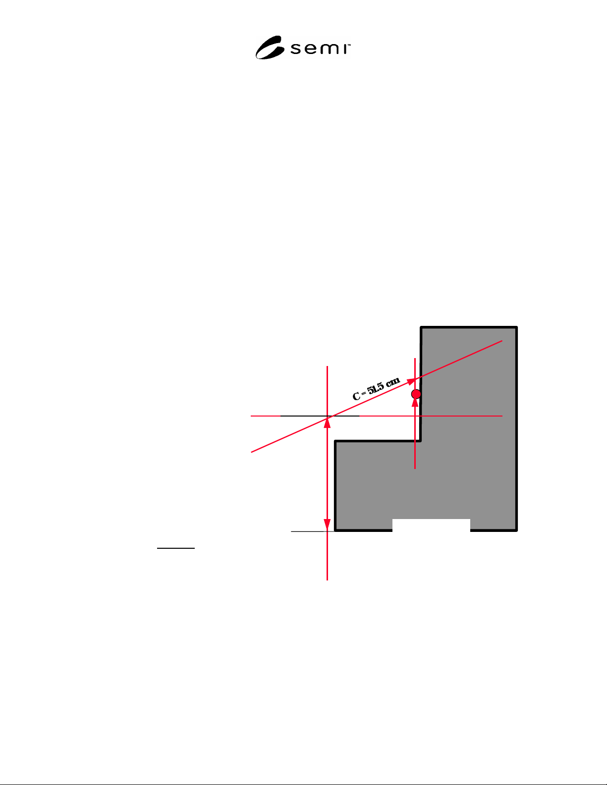
R4-1 INTRODUCTION: Although SEMI S8 limits EMO button heights to 164 cm, it does not explicitly address
the situation where a person must reach over, say, a work surface to reach the EMO button. The calculations shown
below show one method of addressing this situation. Other issues, besides those shown below, must also be taken
into account when locating EMO buttons; see SEMI S2 and SEMI S8.
114 cm
Ex. Standing:
B
2
= C
2
- A
2
If A = 30 cm then
B
2
= 51.5
2
- 30
2
B = 41.8 cm
The button could be located at a
maximum of:
114 + 41.8 = 155.8 cm
from the floor
B
A
NOT TO SCALE
The maximum height allowed for an
EMO is determined by the following
equation: (design for 5% female)
Max height = Shoulder Height + B
Max height should never exceed:
164 cm for standing station
100 cm for sitting station
Where:
A = Length of horizontal barrier to EMO
B = Distance above shoulder
C = Upper limb length for 5% female
(always 51.5 cm)
And for 5% female:
Standing shoulder height = 114.0 cm
Sitting shoulder height = 46.5 cm

SEMI S2-0703a
E
© SEMI 1991, 2004 60
RELATED INFORMATION 5
SEISMIC PROTECTION
NOTICE: This related information is not an official part of SEMI S2 and was derived from practical application by
task force members. This related information was approved for publication by vote of the responsible committee on
October 21, 1999.
R5-1 Seismic Protection Checklist
Supporting Review Criteria for Seismic Protection of Related Components
If the answer to Questions A.1 or A.2 is “No,” or the answer to any other of these questions in the checklist is
“Yes,” then a detailed analysis may need to be performed by a structural or mechanical engineer.
A. Equipment Anchorage
1. Have lateral force and overturning calculations been performed (see example)?
Yes No Comments:
2. Are all modules fastened at a minimum of four points and can the fasteners support the forces identified in
question 1 above?
Yes No Comments:
3. Is it possible that there could be excessive seismic anchor movements that could result in relative
displacements between points of support or attachment of the components (e.g., between vessels, pipe supports,
main headers, etc.)?
Yes No Comments:
4. Is there inadequate horizontal support?
Yes No Comments:
5. Is there inadequate vertical supports and/or insufficient lateral restraints?
Yes No Comments:
6. Are support fasteners inappropriately secured?
Yes No Comments:
7. Is there inadequate anchorage of attached equipment?
Yes No Comments:
NOTE R5-1: One way of judging whether supports, fasteners, or anchorages are “inadequate” or inappropriately secured” is to
determine whether their stress levels under seismic loading stay below the allowable stress levels set by building code. Such
allowable stress levels are typically a fraction < 1 of the yield strength.
B. Equipment Assembly, Installation and Operation
1. Are the materials of construction of the components susceptible to seismic damage?
Yes No Comments:
2. Are there significant cyclic operational loading conditions that may substantially reduce system fatigue
life?

SEMI S2-0703a
E
© SEMI 1991, 2004 61
Yes No Comments:
3. Are there any threaded connections, flange joints, or special fittings?
Yes No Comments:
4. If answer to Question 4 is “Yes,” are these connections, joints, or special fittings in high stress locations?
Yes No Comments:
5. Are there short or rigid spans that cannot accommodate the relative displacement of the supports (e.g.,
piping spanning between two structural systems)? Is hazardous gas piping provided with a “pigtail” (i.e., spiral) or
bent 3 times (z, y, and z direction) to absorb 3-dimensional displacements?
Yes No Comments:
6. Are there large, unsupported masses (e.g., valves) attached to components?
Yes No Comments:
7. Are there any welded attachments to thin wall components?
Yes No Comments:
8. Could any sensitive equipment (e.g., control valves) be affected ?
Yes No Comments:
C. Seismic Interactions
1. Are there any points where seismically induced interaction with other elements, structures, systems, or
components could damage the components (e.g., impact, falling objects, etc.)?
Yes No Comments:
2. Could there be displacements from inertial effects?
Yes No Comments: