semi合集-English.pdf - 第6328页
1 SEMI G65-96 © SEMI 1996, 2004 SEMI G65-96 (Reapproved 1104) TEST METHOD FOR EVALUATIO N OF LEADFRAME MATERIALS USED FOR L-LEADED (GUL L WING TYPE) PACKAGES This test method was technicall y approved by the Global Assem…

SEMI G64-96 © SEMI 1996, 2004 4
APPENDIX 1
SOLDERABILITY TEST
NOTICE: The material in this appendix is an official part of SEMI G64 and was approved by full letter ballot
procedures.
A1-1 Accelerated Environment Simulation
A1-1.1 Determination, due to the environment, may be
simulated by exposure to a hot plate that reproduces the
heat characteristics of assembly (a), and by steam aging
to simulate the storage environment. The following are
methods for accelerated environment simulations (b):
a. Place samples in air on a hot plate or a heat block.
Temperature and duration are detailed in Section
9.3, and represent the heat characteristics of
assembly.
b. Steam aging test is based on MIL-STD-883D,
Method 2003.7, and simulates environmental
conditions.
A1-2 Soldering Parameter
A1-1.2 Baked test specimens shall be dipped into flux
conforming to MIL-P-14256, type-R, for 5 to 10
seconds, and then dipped in a solder bath conforming to
QQ-S-571 for 10 ± 1 seconds at a solder pot
temperature of 230 ± 5°C.
A1-3 Evaluation of Solderability
A1-3.1 Wetting Area — After cleaning solder dipped
specimen with alcohol to remove flux, visually inspect
under a microscope at 10× magnification. Solder must
cover 95% or more of surface area, based on MIL-STD-
883D, Method 2003.7.
A1-3.2 Wetting Time (zero-cross-time) — Solder that
conforms to conditions below is evaluated according to
JIS-C-0053, or may be evaluated by a method
determined by user and supplier for certain leadframe
shapes.
1. Temperature: 230 ± 5°C
2. Dipping speed: 2 mm/second
3. Dipping depth: 2 mm
4. Flux: Rosin flux (MIL-F-14256, type-R)
5. Solder composition: 63 Sn / 37 Pb (QQ-S-571)
NOTICE: SEMI makes no warranties or
representations as to the suitability of the standards set
forth herein for any particular application. The
determination of the suitability of the standard is solely
the responsibility of the user. Users are cautioned to
refer to manufacturer's instructions, product labels,
product data sheets, and other relevant literature,
respecting any materials or equipment mentioned
herein. These standards are subject to change without
notice.
By publication of this standard, Semiconductor
Equipment and Materials International (SEMI) takes no
position respecting the validity of any patent rights or
copyrights asserted in connection with any items
mentioned in this standard. Users of this standard are
expressly advised that determination of any such patent
rights or copyrights, and the risk of infringement of
such rights are entirely their own responsibility.
Copyright by SEMI® (Semiconductor Equipment and Materials
International), 3081 Zanker Road, San Jose, CA 95134. Reproduction of
the contents in whole or in part is forbidden without express written
consent of SEMI.
1 SEMI G65-96 © SEMI 1996, 2004
SEMI G65-96 (Reapproved 1104)
TEST METHOD FOR EVALUATION OF LEADFRAME MATERIALS
USED FOR L-LEADED (GULL WING TYPE) PACKAGES
This test method was technically approved by the Global Assembly & Packaging Committee and is the direct
responsibility of the Japanese Packaging Committee. Current edition approved by the Japanese Regional
Standards Committee on July 23, 2004. Initially available at www.semi.org September 2004; to be published
November 2004. Originally published in 1996.
1 Purpose
1.1 This test method describes an evaluation method
for bending characteristics of leadframe materials used
for L-leaded packages.
NOTE 1: The lead fatigue test described in MIL-STD-
883/2004 is not suitable for evaluating the bending
characteristics of fine pitch leadframes or leadframes used for
L-leaded packages because the method is based on reforming
the leads.
2 Scope
2.1 This test method may be applied to leadframes for
L-leaded packages such as QFP, SOP, TSOP, etc.
2.2 This test method may also be applied to any
leadframe materials with thickness 0.15 mm.
2.3 The test method may be used in trim and form tool
suppliers, leadframe material suppliers, leadframe
manufacturers, and package engineers.
NOTICE: This standard does not purport to address
safety issues, if any, associated with its use. It is the
responsibility of the users of this standard to establish
appropriate safety and health practices and determine
the applicability of regulatory or other limitations prior
to use.
3 Referenced Standards
3.1 Military Standard
1
MIL-STD-983 — Method 2004, Lead Integrity
NOTICE: Unless otherwise indicated, all documents
cited shall be the latest published versions.
4 Terminology
4.1 Definitions
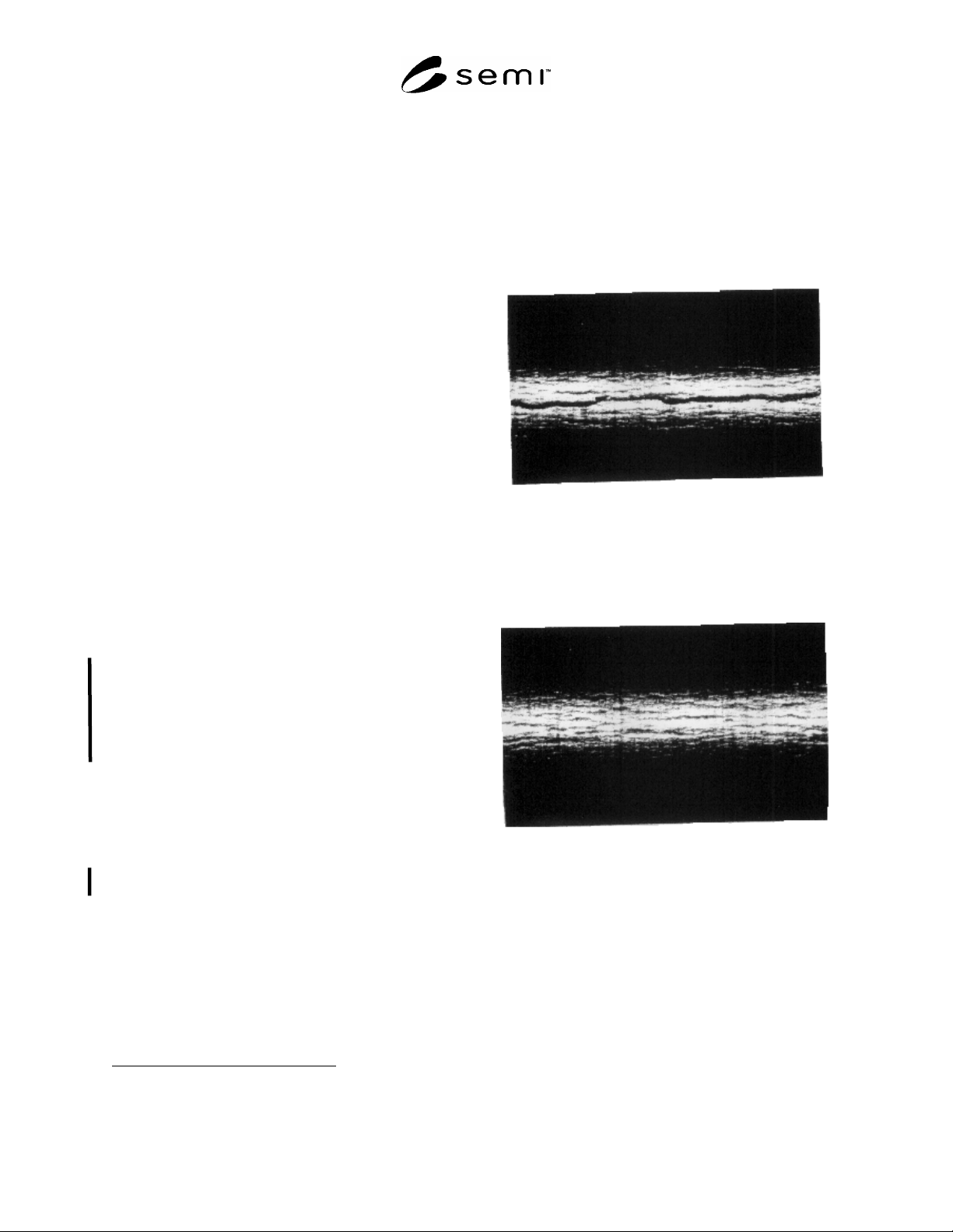
4.1.1 crack (of leadframe) — Micro cleavage or
fracture on surface of outside of lead which is caused
by bending (see Figure 1).
1 United States Military Standards, Available through the Naval
Publications and Forms Center, 5801 Tabor Avenue, Philadelphia,
PA 19120-5099, USA. Telephone: 215.697.3321
Figure 1
Crack
4.1.2 orange peel (of leadframe) — Micro roughness
on surface of outside of lead caused by bending (see
Figure 2).
Figure 2
Orange Peel
4.1.3 spring back — Difference between designed
angle of forming tool and actual lead form angle.
NOTE 2: In this method, the angle of forming tool is 90°.
The value is defined by: Actual lead bend angle 90°.
SEMI G65-96 © SEMI 1996, 2004 2
5 Summary of Method
5.1 The leadframe samples (etched using a standard mask agreed between user and supplier) will be formed using a
“W” forming tool. The resulting form angle is to be measured and surface characteristics such as cracking and
orange peel are to be visible for compliance to the agreed upon specification.
6 Interference
6.1 If the forming tool does not meet the specification, lead movement during forming may result in poor
repeatability.
7 Significance
7.1 Devices manufactured with leadframes of different spring back characteristics may cause board assembly
problems, due to lead positional differences.
7.2 Crack in the leadframe may cause poor contact reliability with board.
8 Equipment
8.1 Tensile Tester — With minimum 9800N force and 1% accuracy.
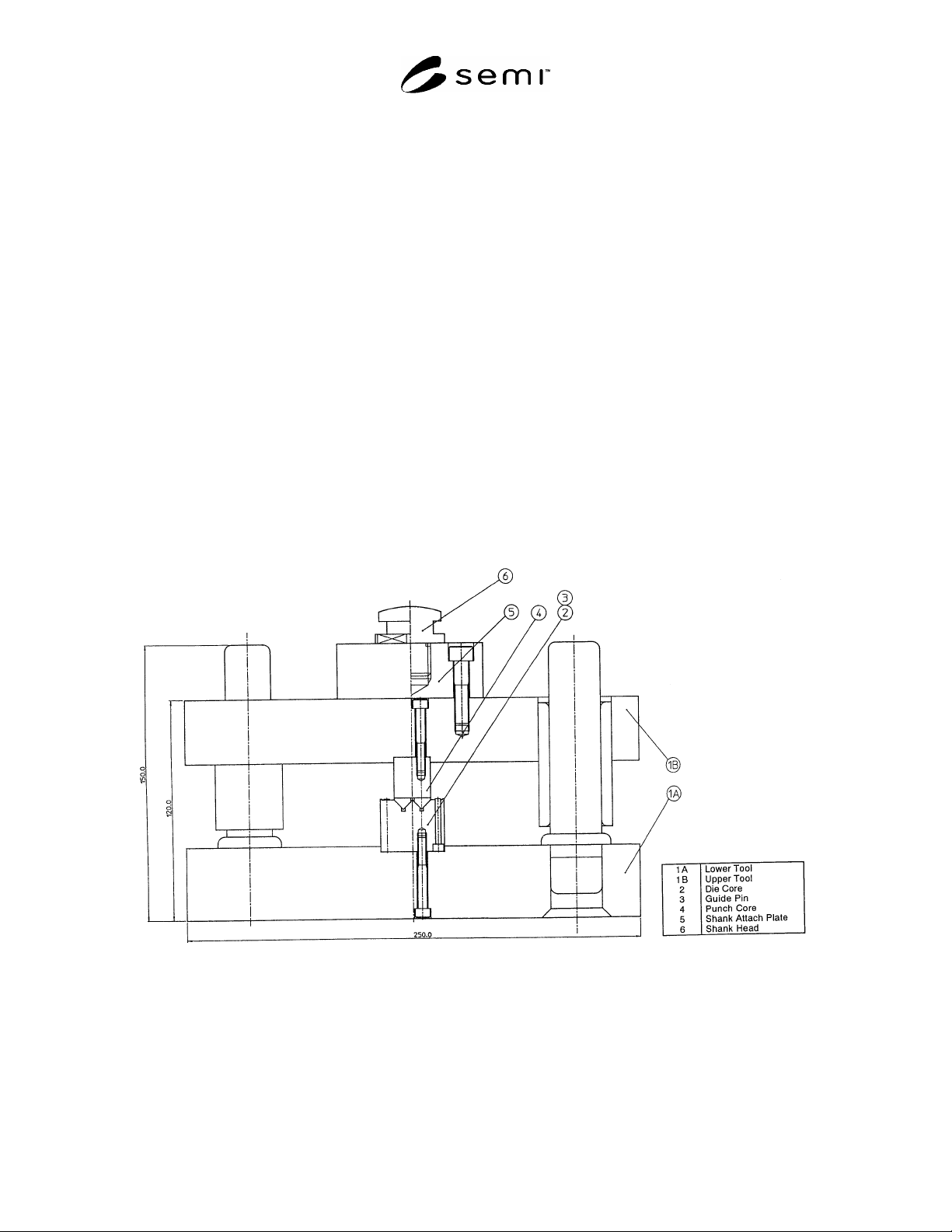
8.2 “W” Forming Tool — With R = 0, 0.1 and 0.2 and form angle of 90°. The dimension and configuration are
shown in Figures 3–7.
Figure 3
W-Bending Test Tool