semi合集-English.pdf - 第3627页
SEMI E139.1-0705 © SEMI 2005 3 6 Conventions 6.1 This section discusses the conv entions used in th is specification for translating UML to XML and for document ing the XML. These conventions are heavily influenced by th…
SEMI E139.1-0705 © SEMI 2005 2
1 Purpose
1.1 The purpose of this document is to define an XML-based format for transferring recipe components. This
includes an XML schema that corresponds to the UML model for the RaP Process Definition Element (PDE) as
defined by SEMI E139. In addition, an XML schema is defined for the Manifest that must be included in the
TransferContainer with the PDE’s during transfer.
2 Scope
2.1 The scope of this document is the faithful representation of the PDE and Manifest definition from SEMI E139
in an XML schema. It will not add new domain information or concepts to the model. The only additions made are
those needed to render a useful XML schema.
3 Limitations
NOTICE: This standard does not purport to address safety issues, if any, associated with its use. It is the
responsibility of the users of this standard to establish appropriate safety and health practices and determine the
applicability of regulatory or other limitations prior to use.
4 Referenced Standards and Documents
4.1 SEMI Standards
SEMI E121 — Guide for Style & Usage of XML for Semiconductor Manufacturing Applications
4.2 OMG Standards
Unified Modeling Language (UML) Specification, Version 1.4, OMG Specification 01-09-67,
(
http://www.omg.org/technology/documents/modeling_spec_catalog.htm
).
4.3 W3C Standards
Canonical XML Version 1.0 — W3C, 15 March 2001 (http://www.w3.org/TR/xml-c14n).
Extensible Markup Language (XML) 1.0 (Second Edition) — W3C, 6 October 2000
(http://www.w3.org/TR/2000/REC-xml-20001006/).
Namespaces in XML — W3C, 14 January 1999 (http://www.w3.org/TR/1999/REC-xml-names-19990114/).
XML Schema Part 0: Primer — W3C, 2 May 2001 (http://www.w3.org/TR/xmlschema-0/).
XML Schema Part 1: Structures — W3C, 2 May 2001 (http://www.w3.org/TR/xmlschema-1/).
XML Schema Part 2: Datatypes — W3C, 2 May 2001 (http://www.w3.org/TR/xmlschema-2/).
XML Path Language (Xpath) — W3C, 16 November 1999 (http://www.w3.org/TR/xpath/).
5 Terminology
5.1 Abbreviations and Acronyms
5.1.1 UML — Unified Modeling Language
5.1.2 W3C — World Wide Web Consortium
5.1.3 XML — eXtensible Markup Language
5.2 Definitions And Acronyms
5.2.1 UML (Unified Modeling Language) — A notation for representing object-oriented designs and views created
by Booch, Rumbaugh, and Jacobson in order to merge their three popular notations plus aspects of other existing
notations into a single object-oriented notation intended to be usable by all.
5.2.2 XML (eXtensible Markup Language) — A markup language used for representing data rich with context and
content in documents and in communications. XML is an extension of SGML, a document-oriented markup
language. It was created by W3C for use on the Internet. XML can represent object-oriented structures.
SEMI E139.1-0705 © SEMI 2005 3
6 Conventions
6.1 This section discusses the conventions used in this specification for translating UML to XML and for
documenting the XML. These conventions are heavily influenced by the SEMI E121 Guide for Style & Usage of
XML for Semiconductor Manufacturing Applications.
6.2 The reader is expected to have a working knowledge of the UML, XML, and Schema specifications (See ¶4.2
and ¶4.3). This document does not provide tutorial information on these subjects.
6.3 Translating UML to XML
6.3.1 This document follows the guidelines for XML as outlined in SEMI E121 “Guide For Style & Usage of XML
for Semiconductor Manufacturing Applications”.
6.3.2 Some of the key guidelines in this specification are summarized here:
Attributes of a class are generally represented as elements such that they can be easily extended by other
applications.
Inheritance is modeled as element extension.
Compositions always turn into contained elements (or contained collections if multiples are allowed).
Associations and Aggregations are modeled as contained elements or arrays wherever possible to simplify the
instance model.
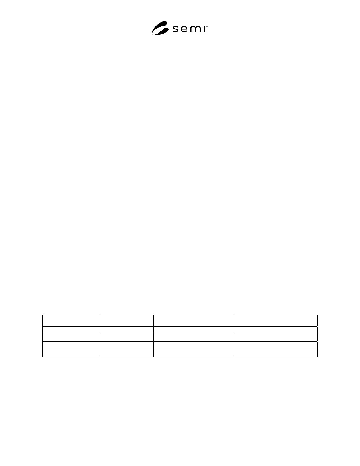
6.3.3 The translation of a UML class to XML is documented using a table format illustrated by Table 1. Note that
the PDE model in SEMI E139 does not include services, so only attribute and association representations are
addressed here. Any superclass information is addressed in the text and the diagrams.
6.4 Translation Table Column Header Description
Attribute or Role Name — If an attribute, the name of the attribute is placed here. If an association (including
aggregation or composition), the role name from the UML diagram is placed here. Compositions are often not
assigned role names. In that case “none” is placed here.
UML Type — If an attribute, the data type of the UML attribute is placed here. If an association, the type of
association is placed here. The possible types are “Composition”, “Aggregation”, or the basic “Association”.
UML defines these three types of association.
XML Element or Attribute — Lists the type of XML construct used to represent the UML attribute or
association.
XML Name/Type — Provides the name and data type of the resulting XML construct. The type may be a
built-in type (for example, xs:string), or a named type defined within the XML schema.
Table 1 Example Translation Table
Attribute or Role Name UML Type XML Element or Attribute XML Name/Type
friend association element Friend: HumanReferenceArray
employees aggregation element Employees: HumanArray
family composition element Family: HumanArray
name string element Name: xs:string
6.5 Documenting The XML With Diagrams
6.5.1 This document provides graphical representations of the included XML. Although no standard graphical
notation for XML could be found, various XML tools have their own notation. This document will use the notation
provided by XMLSPY® from Altova Corporation
1
. There is no requirement for use of XMLSPY® in order to
1 All images/graphics were created using Altova’s XMLSPY®. Copyright 2003 Altova GmbH and reprinted with permission of
Altova.
SEMI E139.1-0705 © SEMI 2005 4
comply with this specification. Figure 1 shows a sample XML diagram that will be used to provide a basis for
explanation of the XML graphical notation used in the rest of the document.
6.5.2 In the diagram, rectangular boxes represent XML elements. Ownership or containment is read from right to
left in the diagrams. In the sample diagram, ParentType contains Child1, Child2, Child 3, and Child 4. In turn,
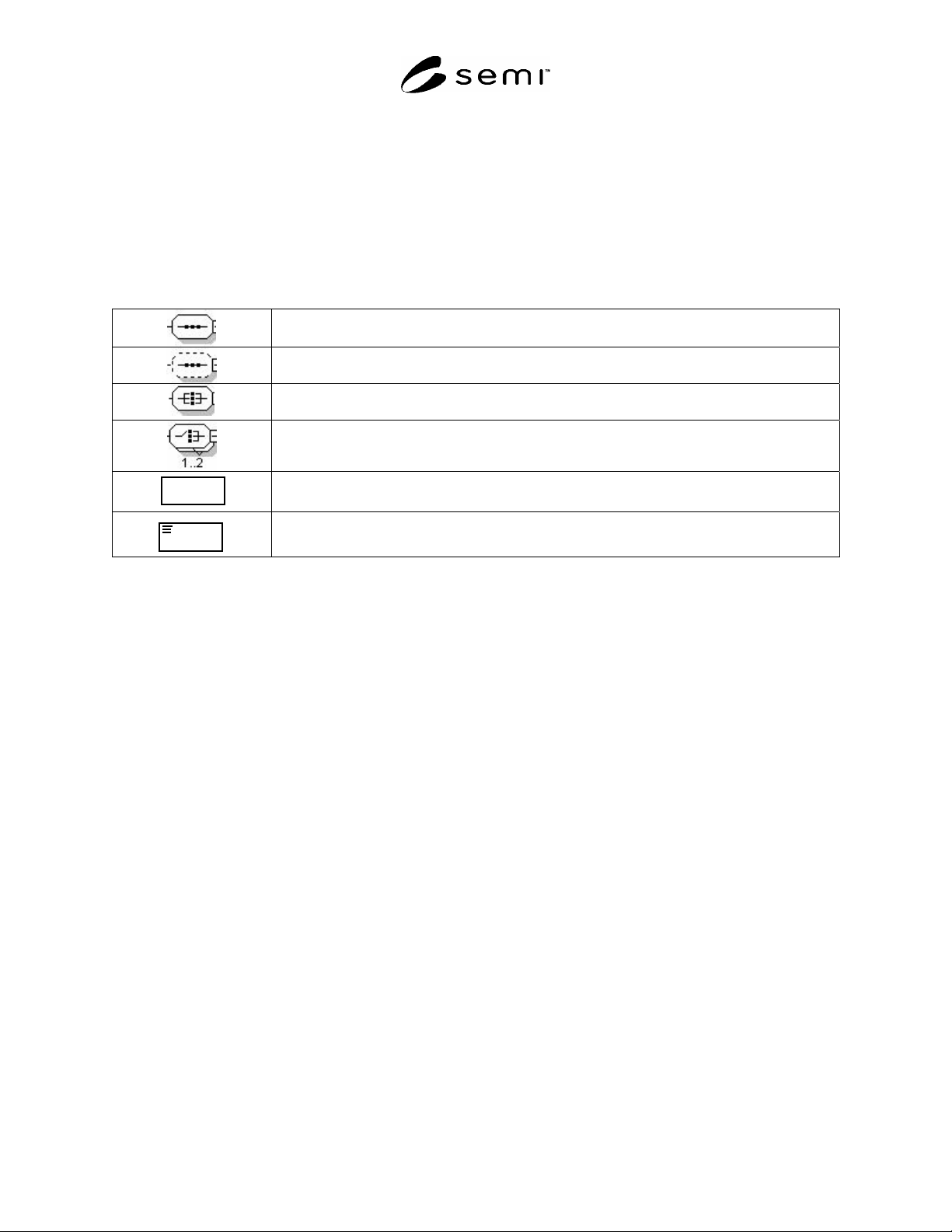
Child2 contains Child2a, Child2b, and Child2c. The additional symbols (8-sided boxes) represent sequences or
choices. See Table 2 for an explanation of these symbols.
6.5.3 Please note that “element”, “sequence”, “all”, and “choice” are XML terms (see the W3C standards
referenced in ¶4.3).
Table 2 Altova XMLSPY® Schema Diagram Symbols
Denotes a required ordered sequence of the right hand elements with a cardinality of one
for each element. (sequence)
Denotes an optional ordered sequence of the right hand elements with a cardinality of one
for each element. (sequence)
Denotes a required, but unordered, sequence of the right hand elements with a cardinality
of one for each element. (all)
Denotes a required choice of the right hand elements. Exactly one or two of the right
hand elements must be present. (choice)
Name
Denotes an element. Optional element if outline is dashed line.
NameName
Denotes an element that contains parsed character data.
6.5.4 A graphic using a solid line is a required element; using a dashed line represents an optional element.
Numbers or ranges in the lower right hand corner represent cardinality. The default cardinality is one.
6.5.5 To simplify a diagram or help focus on a particular aspect, detail may be hidden. The 8-sided symbols have a
small square on the right end. If a minus sign “-“ is in the box, then all detail is shown. If the box contains a plus
sign “+”, then all detail to the right of that symbol is hidden. The example has no hidden detail.