semi合集-English.pdf - 第784页
SEMI E106-1104 © SEMI 2000, 2004 2 3 Limitations 3.1 300 m m Only — This docu ment only covers SEMI standards that are specific to 300 mm, even though other standar ds may appl y to 300 mm equipment. For example, standar…
SEMI E106-1104 © SEMI 2000, 2004 1
SEMI E106-1104
OVERVIEW GUIDE TO SEMI STANDARDS FOR PHYSICAL
INTERFACES AND CARRIERS FOR 300 mm WAFERS
This guide was technically approved by the Global Physical Interfaces & Carriers Committee and is the direct
responsibility of the North American Physical Interfaces & Carriers Committee. Current edition approved by
the North American Regional Standards Committee on July 11, 2004 and August 16, 2004. Initially
available at www.semi.org September 2004; to be published November 2004. Originally published October
2000; previously published March 2003. This document replaces SEMI PR6-0200 in its entirety.
1 Purpose
1.1 This document is intended to help users and
suppliers of 300 mm carriers and production equipment
to understand the complex interdependencies among the
SEMI standards for 300 mm physical interfaces and
carriers and to determine which standards apply to
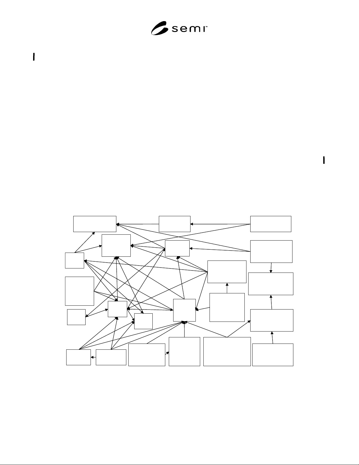
which products. As shown in Figure 1, these standards
are highly inter-related, have many complex
dependencies, and inherit a numbering system (from
legacy 200 mm standards) that is non-intuitive.
2 Scope
2.1 This document describes how the SEMI standards
for 300 mm physical interfaces and carriers work
together. This document also clarifies the requirements
(direct and indirect) on suppliers of each product, and
suggests how users see these standards and options.
NOTICE: This standard does not purport to address
safety issues, if any, associated with its use. It is the
responsibility of the users of this standard to establish
appropriate safety and health practices and determine
the applicability of regulatory or other limitations prior
to use.
M1.15, M8, M28
Wafer
E25
Cluster - Tool
Module Access
E26.1
Radial Cluster -
Tool Footprint
E21.1
Cluster
-
Tool
Module Interface
G77
Frame Cassette
E22.1
Cluster - Tool
End
Effector
M31
FOSB
G74
Tape Frame
E103
SWIF
E47.1
FOUP
E62
FIMS
E15.1
Load
Port
E63
BOLTS-M
E92
Bolts
-
Light
E83
PGV Docking
Flange
E64
Cart
Docking
Interface
E72
Equipment
Footprint, Height,
and Weight
E1.9
Cassette
E85
AMHS
Interoperabiity
E84
Carrier
Handoff
Parallel I/O
E57
Kinematic
Coupling
E110
Indicator/
switch
Placement
M1.15, M8, M28
Wafer
E25
Cluster - Tool
Module Access
E26.1
Radial Cluster -
Tool Footprint
E21.1
Cluster
-
Tool
Module Interface
G77
Frame Cassette
E22.1
Cluster - Tool
End
Effector
M31
FOSB
G74
Tape Frame
E103
SWIF
E47.1
E62
FIMS
E15.1
Load
Port
E92
Bolts
-
Light
E83
PGV Docking
Flange
E64
Cart
Docking
Interface
E72
Equipment
Footprint, Height,
and Weight
E1.9
Cassette
E85
AMHS
Interoperabiity
E84
Carrier
Handoff
Parallel I/O
E57
Kinematic
Coupling
E110
Indicator/
switch
Placement
Figure 1
Complex Relationships and Dependencies Among 300 mm Standards

SEMI E106-1104 © SEMI 2000, 2004 2
3 Limitations
3.1 300 mm Only — This document only covers SEMI
standards that are specific to 300 mm, even though
other standards may apply to 300 mm equipment. For
example, standards not described here include:
metrics documents such as SEMI E10;
minienvironment documents such as SEMI E45
and and SEMI E46;
facilities documents such as SEMI E70;
reticle handling documents such as SEMI E100
which specifies a reticle SMIF pod for 6-inch or
230 mm reticles based on SEMI E19.4; or
safety documents such as SEMI S2, SEMI S8,
SEMI S11 and an upcoming Safety Guideline for
Unmanned Transport Vehicle (UTV) Systems.
3.2 Physical Interfaces and Carriers Only — This
document also does not cover standards that were
generated by committees other than the SEMI Physical
Interfaces and Carriers Committee, even though such
standards may be specific to 300 mm. For example,
standards not described here include:
Information and Control documents such as SEMI
E82; and
Silicon documents such as SEMI M1.15, SEMI
M8, and SEMI M28 (Developmental Wafers).
4 Referenced Standards
4.1 SEMI Standards
SEMI E1.9 — Mechanical Specification for Cassettes
Used to Transport and Store 300 mm Wafers
SEMI E10 — Specification for Definition and
Measurement of Equipment Reliability, Availability,
and Maintainability (RAM)
SEMI E15 — Specification for Tool Load Port
SEMI E15.1 — Specification for 300 mm Tool Load
Port
SEMI E19 — Standard Mechanical Interface (SMIF)
SEMI E19.4 — 200 mm Standard Mechanical Interface
(SMIF)
SEMI E21.1 — Cluster Tool Module Interface 300
mm: Mechanical Interface and Wafer Transport
Standard
SEMI E22.1 — Cluster Tool Module Interface 300
mm: Transport Module End Effector Exclusion Volume
Standard
SEMI E23 — Specification for Cassette Transfer
Parallel I/O Interface
SEMI E25 — Cluster Tool Module Interface: Module
Access Guideline
SEMI E26.1 — Radial Cluster Tool Footprint 300 mm
Standard
SEMI E45 — Test Method for the Determination of
Inorganic Contamination from Minienvironments Using
Vapor Phase Decomposition-Total Reflection X-Ray
Spectroscopy (VPD-TXRF), VPD-Atomic Absorption
Spectroscopy (VPD-AAS), or VPD/Inductively
Coupled Plasma-Mass Spectrometry (VPD/ICP-MS)
SEMI E46 — Test Method for the Determination of
Organic Contamination from Minienvironments Using
Ion Mobility Spectrometry (IMS)
SEMI E47.1 — Provisional Mechanical Specification
for Boxes and Pods Used to Transport and Store 300
mm Wafers
SEMI E57 — Mechanical Specification for Kinematic
Couplings Used to Align and Support 300 mm Wafer
Carriers
SEMI E62 — Provisional Specification for 300 mm
Front-Opening Interface Mechanical Standard (FIMS)
SEMI E63 — Mechanical Specification for 300 mm
Box Opener/Loader to Tool Standard (BOLTS-M)
Interface
SEMI E64 — Specification for 300 mm Cart to SEMI
E15.1 Docking Interface Port
SEMI E70 — Guide for Tool Accommodation Process
SEMI E72 — Specification and Guide for 300 mm
Equipment Footprint, Height, and Weight
SEMI E82 — Specification for Interbay/Intrabay
AMHS SEM (IBSEM)
SEMI E83 — Specification for 300 mm PGV
Mechanical Docking Flange
SEMI E84 — Specification for Enhanced Carrier
Handoff Parallel I/O Interface
SEMI E85 — Specification for Physical AMHS
Stocker to Interbay Transport System Interoperability
SEMI E92 — Specification for 300 mm Light Weight
and Compact Box Opener/Loader to Tool-
Interoperability Standard (BOLTS/Light))
SEMI E99 — The Carrier ID Reader/Writer Functional
Standard: Specification of Concepts, Behavior, and
Services

SEMI E106-1104 © SEMI 2000, 2004 3
SEMI E99.1 — Specification for SECS-I and SECS-II
Protocol for Carrier ID Reader/Writer Functional
Standard
SEMI E100 — Specification for a Reticle SMIF Pod
(RSP) Used to Transport and Store 6 Inch or 230 mm
Reticles
SEMI E101 — Guide for EFEM Functional Structure
Model
SEMI E103 — Provisional Mechanical Specification
for a 300 mm Single-Wafer Box System that Emulates
a FOUP
SEMI G74 — Specification for Tape Frame for 300
mm Wafers
SEMI G77 — Specification for Frame Cassette for 300
mm Wafers
SEMI M1.15 — Standard for 300 mm Polished
Monocrystalline Silicon Wafers (Notched)
SEMI M8 — Specification for Polished
Monocrystalline Silicon Test Wafers
SEMI M28 — Specifications for Developmental 300
mm Diameter Polished Single Crystal Silicon Wafers
SEMI M29 — Specification for 300 mm Shipping Box
SEMI M31 — Provisional Mechanical Specification for
Front-Opening Shipping Box Used to Transport and
Ship 300 mm Wafers
SEMI S2 — Environmental, Health, and Safety
Guideline for Semiconductor Manufacturing Equipment
SEMI S8 — Safety Guidelines for Ergonomics
Engineering of Semiconductor Manufacturing
Equipment
SEMI S11 — Environmental, Safety, and Health
Guidelines for Semiconductor Manufacturing
Equipment Minienvironments
NOTICE: Unless otherwise indicated, all documents
cited shall be the latest published versions.
5 Terminology
5.1 Abbreviations and Acronyms
5.1.1 AGV — automatic guided vehicle (as defined in
SEMI E101).
5.1.2 PGV — person guided vehicle (cart) (as defined
in SEMI E101).
5.1.3 RGV — rail guided vehicle (moving on the floor)
(as defined in SEMI E101).
5.2 Definitions
5.2.1 bilateral datum plane — a vertical plane that
bisects the wafers and that is perpendicular to both the
horizontal and facial datum planes (as defined in SEMI
E57).
5.2.2 BOLTS plane — a plane parallel to the facial
datum plane near the front of the tool where the box
opener/loader is attached (as defined in SEMI E63).
5.2.3 box — a protective portable container for a
cassette and/or substrate(s).
5.2.4 box opener/loader or BOLTS unit — the
equipment component that opens wafer carriers (if
needed) and presents the carriers to the equipment’s
wafer handler for unloading and loading wafers (as
defined in SEMI E63).
5.2.5 carrier handler — receives and passes the
carriers from and/or to the external system (such as the
factory material handling system). A carrier handler of
the internal buffer type has the functions of handling
and storing the carriers. A carrier handler for FOUPs
has the opener(s) for opening and closing FOUPs.
5.2.6 cart — a floor-based carrier transfer vehicle (as
defined in SEMI E101).
5.2.7 cassette — an open structure that holds one or
more substrates.
5.2.8 docking — the act of locating a floor-based
carrier transport vehicle for carrier transfer to/from
equipment (as defined in SEMI E101).
5.2.9 equipment front end module (EFEM) — consists
of the carrier handler that receives carriers from the
factory material handling system on one or more load
ports (as specified in SEMI E15.1), opens the carriers
(if needed), and may include a substrate handler for
unloading and loading wafers from the carrier to the
process part of the equipment (as defined in SEMI
E101).
5.2.10 facial datum plane — a vertical plane that
bisects the wafers and that is parallel to the front side of
the carrier (where wafers are removed or inserted). On
tool load ports, it is also parallel to the load face plane
specified in SEMI E15 on the side of the tool where the
carrier is loaded and unloaded (as defined in SEMI
E57).
5.2.11 fixed buffer – EFEM configuration with carrier
places only on load port units arranged in a load port
group (as defined in SEMI E101).
5.2.12 front-opening unified pod (FOUP) — a box
(that complies with SEMI E47.1) with a non-removable
cassette (so that its interior complies with SEMI E1.9)
and with a front-opening interface (that mates with a