semi合集-English.pdf - 第3792页
SEMI F9-0998 © SEMI 1992 , 1998 4 RELATED INFORM A TI ON 1 SA M PLE TEST DATA SHEET NOT E: This re lated informa tion is not an off icial part of SEMI F9 and is not intende d to modif y or supercede the off icial test me…

SEMI F9-0998 © SEMI 1992, 19983
• 0.5R
• 1.0R
• 1.5R
• 2.0R
• 3.0R
9.8 Fill the submersion tank with isopropyl alcohol to
a minimum height 2.5 cm (1 in) above the top of the
test connection.
9.9 Pressurize the test specimen with an internal air
pressure of 250 kPa (36 psig), regardless of tube size.
9.10 Observe the connection for a minimum of one
minute for bubble leakage (bbl/min) and record on test
data sheet under the column entitled “STRAIGHT”.
9.11 Carefully bend the tube in a uniform 180° arc
with a radius of 3R and clamp the free end to the test
fixture. (See Section 9.7 for specific R value.) Proper
tube length at the clamping point is determined in
Section 9.6.
9.11.1 R value tolerances =
• Tubes with 1.5 cm (0.59 in) O.D. or less = ± 5%
• Tubes with greater than 1.5 cm (0.59 in) O.D. = ±
1%
9.12 Observe the connection for a minimum of one
minute for bubble leakage. Record leakage on the
appropriate area of the test data sheet. If no leakage is
observed, note as “None”.
9.13 Repeat Sections 9.11 and 9.12 for the remaining
tube bend radius of 2R, 1.5R, 1R, and 0.5R, in
descending order.
9.13.1 Should any tube kink prior to achieving 0.5R,
testing of that sample will be discontinued. The radius
at which kinking occurred shall be recorded and noted
as “kink”.
9.13.2 To reduce the effects caused by creep of the
material the total time from initial bending of the tube
until achieving the 0.5R value is to be less than ten
minutes.
9.14 After completion of the first sa mple, replace the
fitting and tube with new specimens and repeat Sections
9.4 through 9.13.2 for a total of three samples.
10 Test Data Sheet
The test data sheet shall include the following
information:
10.1 Date tested.
10.2 Operator and test facility.
10.3 Description of items tested, including:
Tubing — Manufacturer, O.D., wall thickness, part
number, and material type.
Fitting — Manufacturer, type, size, part number, and
material type.
10.4 The actual tube bend radius for each nominal
bend radius.
10.5 The leakage rate, in bubbles per minute, for each
sample at each radius.
NOTE: A sample test data sheet is provided as Related
Information 1.
NOTICE: These standards do not purport to address
safety issues, if any, associated with their use. It is the
responsibility of the user of these standards to establish
appropriate safety and health practices and determine
the applicability of regulatory limitations prior to use.
SEMI makes no warranties or representations as to the
suitability of the standards set forth herein for any
particular application. The determination of the
suitability of the standard is solely the responsibility of
the user. Users are cautioned to refer to manufacturer’s
instructions, product labels, product data sheets, and
other relevant literature respecting any materials
mentioned herein. These standards are subject to
change without notice.
The user’s attention is called to the possibility that
compliance with this standard may require use of
copyrighted material or of an invention covered by
patent rights. By publication of this standard, SEMI
takes no position respecting the validity of any patent
rights or copyrights asserted in connection with any
item mentioned in this standard. Users of this standard
are expressly advised that determination of any such
patent rights or copyrights, and the risk of infringement
of such rights, are entirely their own responsibility.
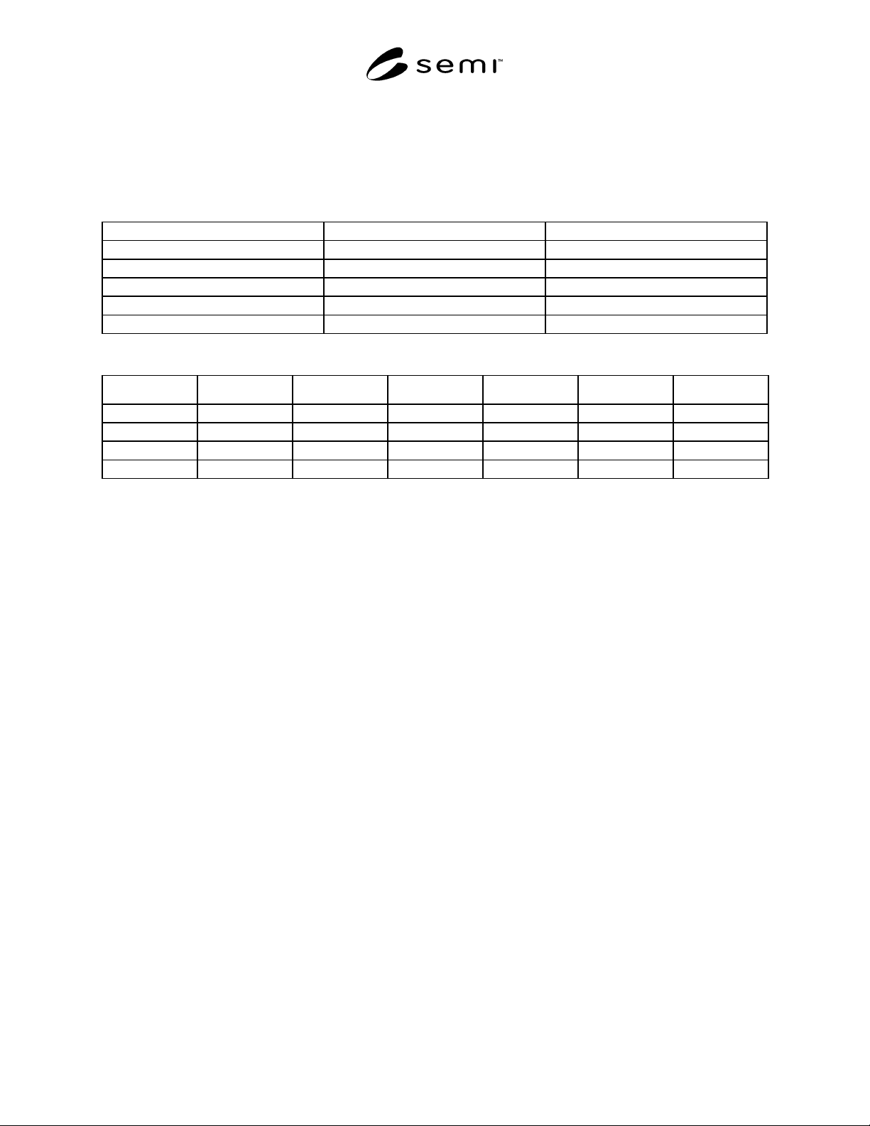
SEMI F9-0998 © SEMI 1992, 1998 4
RELATED INFORMATION 1
SAMPLE TEST DATA SHEET
NOTE: This related information is not an official part of SEMI F9 and is not intended to modify or supercede the official test
method. It has been derived from industry specifications. Publication was authorized by full letter ballot procedures.
Determination of the suitability of the material is solely the responsibility of the user.
Test Date: Operator: Test Facility:
Tube Manufacturer: Fitting Manufacturer:
Tube O.D.: Fitting Type:
Tube Wall Thickness: Fitting Size:
Tube P/N: Fitting P/N:
Tube Material: Fitting Material:
Leakage— (bbl/min.) [ ] = Acutal Tube Bend Radius, cm(s)
3R 2R 1.5R 1R 0.5R
Sample Straight [ ] [ ] [ ] [ ] [ ]
1
2
3
NOTICE: These standards do not purport to address safety issues, if any, associated with their use. It is the
responsibility of the user of these standards to establish appropriate safety and health practices and determine the
applicability of regulatory limitations prior to use. SEMI makes no warranties or representations as to the suitability
of the standards set forth herein for any particular application. The determination of the suitability of the standard is
solely the responsibility of the user. Users are cautioned to refer to manufacturer’s instructions, product labels,
product data sheets, and other relevant literature respecting any materials mentioned herein. These standards are
subject to change without notice.
The user’s attention is called to the possibility that compliance with this standard may require use of copyrighted
material or of an invention covered by patent rights. By publication of this standard, SEMI takes no position
respecting the validity of any patent rights or copyrights asserted in connection with any item mentioned in this
standard. Users of this standard are expressly advised that determination of any such patent rights or copyrights, and
the risk of infringement of such rights, are entirely their own responsibility.
Copyright by SEMI® (Semiconductor Equipment and Materials
International), 3081 Zanker Road, San Jose, CA 95134. Reproduction o
f
the contents in whole or in part is forbidden without express written
consent of SEMI.

SEMI F10-0698 © SEMI 1993, 19981
SEMI F10-0698
TEST METHOD TO DETERMINE THE INTERNAL PRESSURE
REQUIRED TO PRODUCE A FAILURE OF A TUBE FITTING
CONNECTION MADE OF FLUOROCARBON MATERIALS
1 Purpose
1.1 This method provides a uniform procedure to
determine the internal pressure required to produce
failure of fitting connections made of fluorocarbon
materials.
2 Scope
2.1 This method can be used to characterize tube
fitting connections on the basis of test data developed
under the conditions described herein, but the results
are not intended to imply a performance rating.
2.2 Tube defined in this method has a circular cross
section and is made of fluorocarbon materials.
2.3 Tube fittings defined in this method are made of
fluorocarbon materials for all parts in contact with the
internal fluid.
2.3.1 Parts such as a nut or gripper are not limited to
being made of a fluorocarbon material.
2.4 Only the seal between the tube and tube fitting
being evaluated is within the scope of this document.
All other threaded seals are beyond the scope of this
document.
2.5 When using this method for making comparisons
among various tube fittings and/or manufacturers, the
user must be specific in the selection of the tube and
tube fittings to be evaluated.
2.6 The International System of Units (SI) is used as
the standard unit of measure in this document. The U.S.
Customary units are in parentheses for reference
purposes only and may have been rounded to the
nearest whole value.
3 Referenced Document
3.1 ASTM Standard
1
ASTM D 1599 — Test Method for Short-Time
Hydraulic Failure Pressure of Plastic Pipe, Tubing, and
Fittings
4 Summary of Method
4.1 This test method consists of pressurizing tube
fitting connections made of fluorocarbon materials to
1 American Society for Testing and Materials, 100 Barr Harbor
Drive, West Conshohoken, PA 19428-2959
failure by continuously increasing the internal hydraulic
pressure. New tubing and fitting samples are required at
each specific elevated fluid temperature condition, and
failures are to occur within 60 to 70 seconds from initial
exposure to the high pressure fluid.
5 Significance and Use
5.1 In the manufacturing of semiconductor products,
many types of hazardous chemicals and solvents are
required. As a result, tubing and various fitting designs
made of fluorocarbon materials (which are chemically
resistant to these fluids) are used to transport those
fluids. It is important to control the testing process
when evaluating various fitting designs, so that accurate
comparisons of the pressure limits can be made.
5.2 It is the intent of this method to provide a
procedure to determine the maximum pressure limits of
tube fitting connections made of fluorocarbon
materials. By using this method, accurate comparisons
of various tube fitting designs can be achieved.
5.3 The results obtained when usin g this method are
applicable only to conditions that specifically duplicate
the procedures used within this method.
5.4 When using this test method, it is assumed that the
test specimens are truly representative of the material
and manufacturing process specified for that product.
Departure from this assumption could introduce
discrepancies that are greater than those introduced by
departure from the details of the procedure outlined in
this method.
6 Terminology
6.1 characterize — To describe the quality of.
6.2 failure — Any external leakage of fluid through
the tube wall or the tube fitting connection, whether it
be catastrophic or a slow leak.
6.3 free end closure — A metal tube fitting connection
which is securely fastened to the tube and does not
contribute to the restraint of the test specimen.
6.4 isolation valve — A valve used to separate the
high temperature fluid from the high pressure fluid or to
separate the samples from each other.
NOTE: This definition is used in only this test method.