semi合集-English.pdf - 第4596页
SEMI D35-1103 E © SEMI 2003 8 ~ Inverter High v oltag e side Ground Electrode Minimal discharge Stray capacit ance ~ Inverter High v oltag e side Ground Electrode Minimal discharge Stray capacit ance ~ Inverter High v ol…

SEMI D35-1103
E
© SEMI 2003 7
RELATED INFORMATION 1
STARTING VOLTAGE OF COLD CATHODE FLUORESCENT LAMP
(CCFL)
NOTICE: This related information is not an official part of SEMI D35 and was derived from Japan Backlight TF.
R1-1 Phenomenon of CCFL Discharge
Starting
R1-1.1 Although the phenomenon of CCFL discharge
starting shows the similarity to that of low gas pressure
discharge starting, a high frequency lighting circuit
(inverter) with approximately 30–100 kHz is mostly
used to discharge and so it is affected by stray
capacitance.
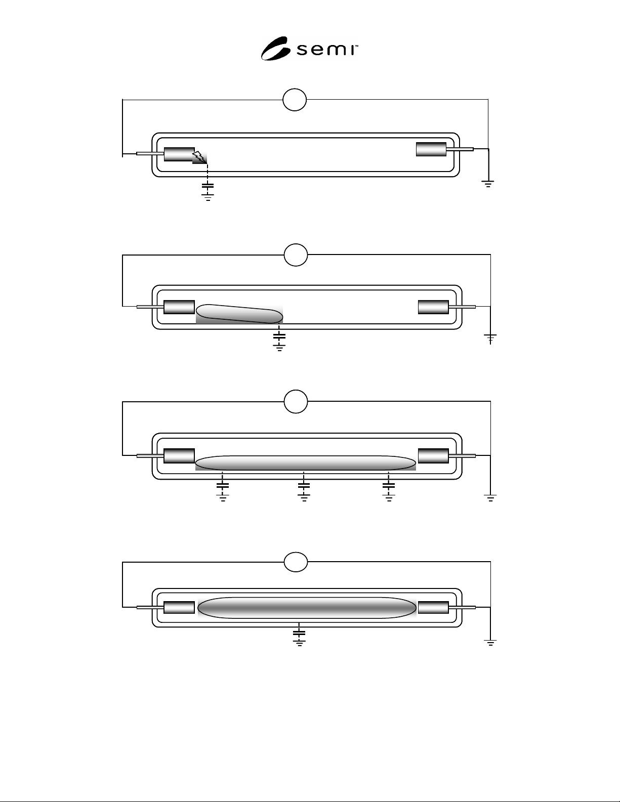
R1-1.2 When the secondary voltage of inverter is
stepping up from a sufficiently low voltage gradually,
an emission area appears near the electrode connected
to higher voltage side. (See Figure R1-1 1
st
Phase).
This means that the discharge starts between the
electrode and ground level of discharge circuit through
the stray capacitance, and a spark after dark current
takes place in the discharge space in the tube. In the
discharge, the other electrode is the tube wall (glass or
fluorescent substance); the formation of dielectric
barrier discharge and the existence of the secondary
electron supply system to the discharge space can be
considered and thus the discharge seems sustainable.
Therefore, the emission around the electrode is judged
to be the emission mainly by negative glow of glow
discharge.
R1-2 From Discharge Starting to Stable
Lighting Mode
R1-2.1 After the discharge takes place near the
electrode and the secondary voltage of the inverter
increases gradually, the emission area near the
electrode grows longer accordingly. (See Figure R1-
2.) This means that a positive column is generated by
applied voltage to have such the length as corresponds
to the value of resistance based on the applied voltage.
When the voltage is applied furthermore, the emission
area (i.e. positive column) between two electrodes is
generated finally. (See Figure R1-3 2
nd
Phase.)
However, if the tube is thin and long and the stray
capacitance is relatively greater to the discharge circuit,
the ratio of current that flows through the stray
capacitance is still large at this phase. With the
increase of the inverter secondary voltage, the ratio of
current that flows in the tube also increases and most of
the current flows in the tube because the impedance of
discharge path decreases on the contrary due to
negative characteristics of discharge. (See Figure R1-4
3
rd
Phase.)
R1-2.2 Each voltage applied at these three phases may
be called starting voltage at the first phase, or stable
discharge voltage or tube current at the third phase, for
example. Sometimes it could be hard to distinguish the
second phase from the third phase. In addition, since
the second phase is hardly observed by the tube designs
(for the tube length, outer and inner diameters of tube,
pressure and composition of filler gas, and peripheral
members of tube), it looks as if the first phase shifted to
the third phase suddenly. This is because the stray
capacitance is so big that the current cannot flow into
the tube, the discharge surges immediately after the
current flows into the tube, the impedance of the
discharge path decreases due to the negative
characteristics and a large amount of current flows in
the tube all of a sudden.
R1-2.3 From the viewpoint of discharge phenomenon,
the voltages applied to the tube at the first and third
phases are important. Especially the voltage applied at
the third phase should be noted practically. (The
voltage applied at the second phase may be noted also.)
R1-3 Cautions at Discharge Starting
R1-3.1 At the discharge starting, coefficient of
discharge gas and coefficient of electrode are
involved. These coefficients contain the pressure of
discharge gas (particle density) as a parameter.
Especially when the mercury is filled in, the control of
ambient temperature becomes very important because
the mercury vapor (particle density) pressure changes
sensitively to the ambient temperature.
R1-3.2 In addition, the lighting circuit is usually built
for AC, the reduction of unnecessary stray capacitance
base on frequency shall be required. As the impact of
stray capacitance becomes greater especially when the
tube is thin and long, sufficient consideration shall be
given.
SEMI D35-1103
E
© SEMI 2003 8
~
Inverter
High voltage side
Ground
Electrode
Minimal discharge
Stray capacitance
~
Inverter
High voltage side
Ground
Electrode
Minimal discharge
Stray capacitance
~
Inverter
High voltage side
Ground
Electrode
Minimal discharge
Stray capacitance
~
Inverter
High voltage side
Ground
Electrode
Minimal discharge
Stray capacitance
Figure R1-1
1
st
Phase of CCFL Discharge Starting
~
Positive column
~
Positive column
~
Positive column
Figure R1-2
From 1
st
Phase to 2
nd
Phase of CCFL Discharge Starting
~~~~
Figure R1-3
2
nd
Phase of CCFL Discharge Starting
~~~
Figure R1-4
3
rd
Phase of CCFL Discharge Starting

SEMI D35-1103
E
© SEMI 2003 9
RELATED INFORMATION 2
DARK CHARACTERISTICS OF DISCHARGE LAMP
NOTICE: This related information is not an official part of SEMI D35 and was derived from Japan Backlight TF.
R2-1 Start of Discharge Lamp
R2-1.1 When a discharge lamp is activated, there must
be electrons (initial electrons) in the discharge space
generally. In order to start up, it is necessary to apply
an electric field, accelerate the initial electrons, excite
and ionize gaseous particles, and establish discharges
(keep up discharges) in the discharge space. At that
moment, the initial electrons are said to have relation to
the continuity of discharges at random, and the
combinations of the status of a lamp when
manufactured, history of on/off of lighting, various
factors of a discharge lamp, and lighting circuits are
involved.
R2-1.2 For these reasons, in terms of the start-up of a
discharge lamp, initial electrons are required and there
are probability factors to be considered, and so the
discharge start-up time delay should be observed
statistically.
R2-2 Dark Characteristics of Discharge Lamp
and Remedy
R2-2.1 A discharge lamp usually starts up in a bright
place even when the initial electron source is not
provided especially. It is considered that this is because
the external light gives energy to materials (gas,
electrode, etc.) inside the discharge space to emit
electrons (photoelectrons) as an initial electron.
However, in order to activate the discharge lamp in a
dark place, the photoelectron cannot be used. There are
electron sources such as natural radiation as the other
initial electrons (cosmic rays and radian from the earth)
but these are not enough to get initial electrons at
present.
R2-2.1.1 Since the initial electrons in the discharge
space in the darkness decrease greatly, the discharge
start-up time delay, which is from the voltage-applied
time to the start-up time, tends to be salient. This is
defined as dark characteristics.
R2-2.2 In order to start up a discharge lamp within a
limited time, the method to supply positively initial
electrons in a discharge space is needed. For example,
regarding a fluorescent lamp for ordinary lighting
purpose, its negative electrode is preheated before the
start-up. As a result, thermoelectrons, which are emitted
from the emitter applied to the negative electrode, are
used as an initial electron. For a glow starter,
bremesstrahlung electrons by radioisotope (RI) built in
the electrodes are employed. In addition, there are
other methods such as applying high-voltage to supply
electrons from the electrodes (field emission) and
supplying photoelectrons by turning on another light
source (light bulb) located nearby a discharge lamp
before its start-up.
R2-2.3 In terms of a discharge lamp used as an LCD
backlight, the conventional remedies have not been
utilized because it must have compact cathode
electrodes, the RI is hardly used from the
environmental view point, the output voltage for an
inverter of high-frequency lighting circuit is limited,
and the space is too small to built another light source
in it. Thus, unique methods have been studied.
Nowadays, the followings, such as exposing a metal
oxide that emits exoelectrons
*1
in the discharge space,
forming spattering layers
*2
on the wall near cathode
electrodes by lighting a discharge lamp for a certain
time, and making a compound of materials with low
work function
*3
into electrodes or placing it near
electrodes, are performed.
R2-3 Theory on Discharge Start-up Time Delay
R2-3.1 The equation on the discharge start-up time
delay is as follows.
= 1/(P·Q) ----------------------------- (1)
where
: average discharge start-up time delay (sec)
P: percentage of one electron that discharges ( /particle)
Q: number of initial electrons (particle/sec)
R2-3.2 In Q factors mentioned before, such as the
photoelectrons
*4
, thermoelectrons by external light,
electrons emitted by field emission, electrons by natural
radiation, electrons by RI, and exoelectrons, and in P
factors, such as the voltage applied to a discharge lamp,
filler gas pressure, kind of gases, electrode materials,
impact of residual impure gases and concessionary
shape of electrode, are involved.
R2-3.3 Here, if a maximum value “1” is set to P by
adjusting a discharge lamp and lighting circuit and if at
least one particle of electron per second exists in a
discharge space, will be 1 second. Usually P is
considered to be the order of 10
-3.
If becomes
approximately 1 second, the initial electrons with order
of 10
3
particles per second will be required, and for 0.1