semi合集-English.pdf - 第1322页
SEMI E5-1104 © SEMI 1982, 2004 264 a TEST command immediat ely before it, s ubject to the block checki ng limitations describe d elsewhere. CNAME = TEST CCODE = 10 BCDS = 5,6, 8 IBCDS = 3 N BCDS = none ACDS = 100.2 IACDS…

SEMI E5-1104 © SEMI 1982, 2004 263
R1-4.3 Equipment Process Capabilities Data
R1-4.3.1 The underlying assumption of SECS-II
formatted process programs is that processing
instructions for equipment can be expressed as
sequences of commands with parameters. Commands
are integer codes which tell the machine what to do.
The parameters of each command are numeric (integer
or floating point) values, Boolean values, or text strings
which specify how to carry out the particular command.
This provides a very flexible structure for building
process programs but does not provide the specific
information (code values, types and number of
parameters, legal parameter values, etc.) required by a
host system to generate a process program for a
particular piece of equipment. Under SECS-II, this
information is provided to a host via the machine’s
Equipment Process Capabilities Data or PCD.
R1-4.3.2 A PCD provides three levels of information
global data pertaining to the entire process program;
definition of each possible command understood by the
machine; and definition of each command parameter.
Global process program definition data consist of
MDLN, SOFTREV, CMDMAX, BYTMAX, and the
list of command descriptors.
R1-4.3.3 MDLN and SOFTREV provide the same data
to the host as the equipment’s response to the S1,F1
host interrogative, “Are you there?” They are included
in the PCD to provide a means of distinguishing
between PCDs for different machines and revisions of
PCDs for the same piece of equipment. Also, when a
process program is generated, the MDLN/SOFTREV
values of the PCD are provided in the process program
to allow the machine an unambiguous method of
determining if the process program was generated from
a PCD it understands.
R1-4.3.4 BYTMAX and CMDMAX are two integer
values which allow the equipment to limit the size of
the process program which will be generated.
BYTMAX specifies the maximum number of bytes a
process program may occupy. CMDMAX specifies the
maximum number of commands which may appear in
the process program. Either value may be zero, which
indicates that no maximum limit is being imposed by
the equipment.
R1-4.3.5 The PCD command list identifies (in no
particular order) each of the unique operations its
associated machine is capable of performing. These
operations may correspond to processing operations of
the equipment (bake, spin), initialization of equipment
components (set beamline controls), definition of data
values referenced by later commands (define bond
coordinates or inspection points), or even “pseudo-
operations,” which allow conditional execution of the
process program (go to X; if temperature out of range,
then go to y; repeat ramping until speed 200; etc.).
R1-4.3.6 Each command in the PCDlist has a number
of data values associated with it which provide the host
with the command’s personality. These are CCODE,
CNAME, RQCMD, BLKDEF, BCDS, IBCDS,
NBCDS, ACDS, IACDS, NACDS, and the commands
parameter list.
R1-4.3.7 CCODE defines the unique numeric code
which the equipment recognizes as representing the
command being defined. CNAME is a text string
which hopefully describes the function of the
command. The string must be unique for each
command since humans generating process programs at
the host will use them, and the host process program
generator will translate the CNAME to the
corresponding CCODE.
R1-4.3.8 RQCMD. This Boolean value allows
equipment to specify whether or not a command must
appear at least once within their process program. If
true, the command must be used. If RQCMD is set
false, the command may or may not be used in the
process program at the discretion of the person creating
the process program.
R1-4.3.9 In addition to the information the PCD
provides on allowed data content within a process
program, it also can provide information to the host on
possible interdependencies between the commands.
Specifically, through the PCD the host can know such
things as: command code A must appear before
command code B; command code A must come after
command code D; command code A must immediately
precede command code X; command code A must not
come before command code E; command code A must
not come after command code F; and/or command code
A must immediately come after command code T.
Each of the PCD entries, BCDS (before codes), ACDS
(after codes), IBCDS (immediately before codes),
IACDS (immediately after codes), NBCDS (not before
codes), and NACDS (not after codes), is a SECS item
which may contain one or more command codes. Each
particular item defines the relation to be satisfied. The
elements of the item identify the command codes which
are to satisfy the relation with the command being
defined. A zero length item indicates that no
restrictions apply for that type of checking. For
example, if the values of the various fields take on the
values shown in Figure R1-1, the host process program
editor will assure that the TEST command (code 10)
will occur before commands with codes 5, 6, and 8; that
it will come after commands with codes 100 and 2; that
TEST will not appear after the command with code 20;
and that each occurrence of command code 3 will have
SEMI E5-1104 © SEMI 1982, 2004 264
a TEST command immediately before it, subject to the
block checking limitations described elsewhere.
CNAME = TEST
CCODE = 10
BCDS = 5,6,8
IBCDS = 3
N
BCDS = none
ACDS = 100.2
IACDS = none
N
ACDS = 20
Figure R1-1
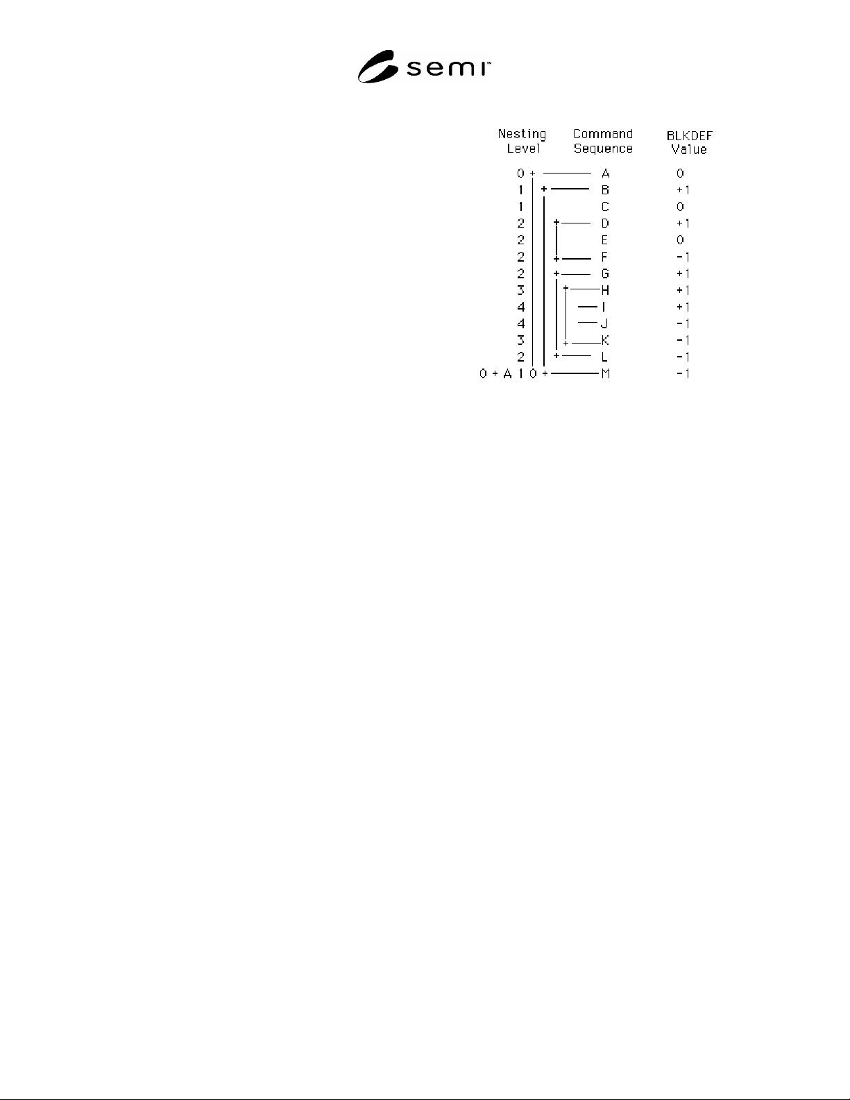
R1-4.3.10 Associated with before/after checking is the
concept of a block which allows setting of limits on
before/after checking. A block consists of a start block
command, a block terminator command and possibly
body commands, commands which are included
between the start and terminator commands. There are
no specific command codes for start, or terminator
commands in SECS-II formatted process programs.
Instead, being a start block, terminator block, or body
command is merely an attribute of each command
defined in the PCD. The field BLKDEF defines this
attribute for each command. A positive one indicates
the command starts a new block. Zero indicates that
the command is a body command and neither starts nor
terminates a block. A value of negative one indicates
that the command is a terminator command.
R1-4.3.11 Before/after checking for a particular
command is performed only with other commands
within the same block. To be within the same block, a
command must have the same nesting level as the
command of interest or the command must be a
contained block.
R1-4.3.11.1 The example data in Figure R1-2 shows
six grouping of commands for before/after checking:
(A,B',N), (B,C,D',G',M), (D,E,F), (G,H',L), (H,I',K),
(I,J). A letter followed by an apostrophe (') indicates a
block which has been collapsed to a command and has
the before/after attributes of its start block command.
Note that body and terminator commands occur in only
one grouping, while block start commands occur in
two. Also, note that the outermost block is assumed to
begin with the first command of the process program
and to end with the last command.
Figure R1-2
R1-4.3.12 Each command’s parameter list defines the
parameters required by the equipment to carry out each
particular command. The order in which each
parameter descriptor appears in the PCD parameter list
also defines the order in which parameters will appear
in a process program command parameter list. Each
parameter is one of three possible types: numeric, text,
or Boolean.
R1-4.3.13 Regardless of parameter type, the first four
elements of any parameter descriptor list are the same.
The first field, PNAME, specifies the text string which
names the parameter. This data will be displayed by a
host when prompting a human for the parameter data.
The second field, RQPAR, specifies if the value must
be specified at the time the process program is
generated (true) or if specifying the data is optional
(false). The third field, PDFLT, identifies the type of
data to be accepted for this parameter as well as
providing default values to include in the process
program if the RQPAR is false and no data is input for
the parameter when the process program is generated.
PDFLT will have zero length if no default value is
provided.
R1-4.3.14 The final field, PMAX, specifies the
maximum length of the parameter data placed in a
process program. For numeric and Boolean data, it
specifies the maximum number of data entries in the
SECS-II item. For a string parameter, it specifies the
maximum number of characters acceptable to the
machine. In either case, negative values are invalid and
a value of zero indicates there is no length restriction.
R1-4.3.15 For numeric and Boolean parameters which
are multi-valued items, usage of PDFLT becomes a bit
more complex. In these cases, PDFLT may also be a

SEMI E5-1104 © SEMI 1982, 2004 265
vector of values. When default values are to be
included in a process program, the entry of the default
vector in the same ordinal position as the parameter
entry requiring the default is used. If the parameter is
allowed to have N entries but only M defaults are
provided, the last N-M parameter entries will have no
defaults.
R1-4.3.16 If the numeric or Boolean vector parameter
is required to be entered, PDFLT will contain no default
data values, but dummy values must be provided so that
the length of the item specifies the minimum number of
entries the equipment expects to receive for the
parameter. If this minimum number of entries exceeds
the maximum number of entries allowed for the
parameter (PMAX), then only PMAX entries will be
provided in the process program.
R1-4.3.17 Numeric parameters may be any of the
SECS recognized floating point or integer data types.
PDFLT identifies the particular type. ULIM and LLIM
will be of the same data type and specify the range of
legal values for the parameter (LLIM x ULIM).
UNITS is a character string formed according to E5,
Section 12, which specifies the expected units of
measure of the numeric value. RESC specifies whether
the resolution of the data item to be entered is to be in
terms of a fundamental increment or significant digits.
In the case of the former, RESV will be of the same
type as the expected parameter and will specify the base
increment. In the case of the latter, RESV will be an
integer and will specify the number of significant digits
to accept for the parameter.
R1-4.3.18 In addition to the standard fields described
above, string parameter descriptors have one unique
field. This field provides a set of template strings. A
text parameter will be assumed valid by a host process
program generator if it matches one of the template
strings. A match occurs if the input string is at least as
long as the corresponding template and each position of
the template and data strings match. A null string
specified as a template will result in a match with any
data string. A null data string will match only a null
template string. A null template list indicates all strings
are acceptable to the equipment.
R1-4.4 Equipment Capabilities Descriptor Availability
R1-4.4.1 Ideally, each piece of equipment should be
able to respond to a host PCD request at any time.
However, inasmuch as an equipment’s PCD may be
rather large and the equipment may have limited
storage capacity, constant availability may be
impossible. In these cases, some compromise will have
to be made such as making it available only at machine
initialization or when idle. In extremely severe cases,
an equipment manufacturer may have to provide the
PCD data with the rest of the machine documentation,
requiring his customer to manually enter the data into
his host system.
R1-4.4.2 In light of this difficulty, host systems should
maintain copies of PCD’s for each piece of equipment
under its control and not expect to be able to obtain the
PCD from the machine whenever it is required. Doing
so, in fact, will permit more flexible process program
development in the host, allowing creation of process
programs even when equipment is not online and
encourage the use of formatted process programs by
equipment manufacturers.
R1-5 Suggested Baseline SECS Equipment
Implementation
R1-5.1 Purpose and Scope
R1-5.1.1 This document provides a recommendation
prepared by the Rigid Disk Subcommittee for
generating a baseline implementation of the SECS
(SEMI Equipment Communication Standard) standards
on production process and test equipment. This
document is not a tutorial to aid in understanding SECS
but rather serves as an introduction to the requirements
of SECS, and a brief guide to the selection of SECS
messages for equipment. Actual system requirements
of many implementations are beyond the scope of this
document. The full standards, SEMI Equipment
Communications Standard I (SECS-I), SEMI E4 and
SEMI Equipment Communications Standard II (SECS-
II), SEMI E5 should be consulted by all users.
R1-5.2 Introduction
R1-5.2.1 The SECS standards are an existing and
developed set of communication standards currently
used by the semiconductor and other industries to
support automated production. The standards provide a
means for communicating information and control
between production equipment and a “host” computer.
This transfer of information and control can be used to
provide production tracking and location of WIP
(Work-In-Process), scheduling of WIP and control of
material transfer at the equipment. The process
measurements and records can be used to provide
process engineers with a database for statistical process
control. SECS messages are appropriate to a wide
variety of applications, including measurement,
processing, and material transport equipment.
R1-5.3 SECS-I Standard
R1-5.3.1 SECS-I defines the lower protocol layers of a
point-to-point interface between equipment and a host
computer system. The standard requires a simple, well
understood physical interface, RS-232. The SECS-I
protocol allows the equipment control over the