semi合集-English.pdf - 第4083页
SEMI F57-0301 © SEMI 200 0, 2001 4 7.3 Ioni c Contamination 7.3.1 Im portance of Test: Ionic cont a mi natio n can have a corros ion and/or etching effect on semiconductor dev ices d uring fabrication, causing immediate …

SEMI F57-0301 © SEMI 2000, 20013
manufactured polymer components meet regulatory
requirements in each location.
4 Referenced Documents
NOTE 1: As listed or revised, all documents cited shall be the
latest publications of adopted standards.
4.1 SEMI Standards
SEMI E49.7 — Guide for Subsystem Assembly and
Testing Procedures - Polymer Systems
SEMI F40 — Practice For Preparing Liquid Chemical
Distribution Components for Chemical Testing
SEMI S2 — Safety Guideline for Semiconductor
Manufacturing Equipment
4.2 ASTM Standards
2
ASTM D4327 — Anions in Water by Chemically
Suppressed Ion Chromatography
ASTM D4779 — Total, Organic, and Inorganic Carbon
in High Purity Water by Ultraviolet (UV) or Persulfate
Oxidation, or Both, and Infrared Detection
ASTM D5904 — Standard Test Method of Total
Carbon, Inorganic Carbon, and Organic Carbon in
Water by UV, Persulfate Oxidation and Membrane
Conductivity Detection
4.3 ISO Standards
3
ISO 1167 — Plastic pipes for the transport of fluids -
Determination of the resistance to internal pressure
ISO 12162 — Thermoplastic materials for pipes and
fittings for pressure applications - Classification and
designation - Overall service (design) coefficient
5 Terminology
5.1 Definitions
5.1.1 Liquid Chemical Distribution System — the
collection of components and subsystems used to
deliver liquid process chemicals from a source location
to a point of use.
5.1.2 Ultrapure Water Distribution System — the
collection of components and subsystems used to
deliver ultrapure water from a source location to a point
of use.
2 American Society for Testing and Materials, 100 Barr Harbor
Drive, West Conshohoken, PA 19428-2959, USA
3 International Organization for Standardization, 1 rue de Varembé,
Case postale 56, CH-1211 Genève 20, Switzerland
6 Ordering Information
6.1 Device manufacturers may use this standard when
procuring facilities or processing equipment to specify
required component performance to the supplier.
Facilities services and process equipment suppliers may
also use this document to specify performance
requirements to component and subassembly suppliers.
6.2 Orders for polymer components or subassemblies
in accordance with this standard shall include the
specification number and date of issue.
7 Purity Requirements
7.1 The values found in Tables 3 t hrough 6 were
constructed from existing databases of high purity
grades of PVDF and PFA. They represent
characteristics of piping system polymer components,
which are currently providing end-users with
satisfactory results. Other materials with other particle
leach out or surface roughness characteristics may or
may not be acceptable. The end-user may need to test
such materials to determine if they will meet both the
static values of this document as well as any final
delivered fluid requirements.
7.2 Particle Contribution
7.2.1 Importance of Test: Particles released from
within polymer components can come into direct
contact with wafers and cause unwanted surface
contamination or disrupt photolithography process
steps, thereby decreasing yields.
7.2.2 Particle contribution specificat ion and testing are
restricted to polymer components as indicated in Table
1.
7.2.3 Polymer components shall conform to the
particle contribution specifications appearing in Table
2.
7.2.4 A Rinse Time Test (see Table 2) provides a
measure of the particle shedding from a component
when it is initially removed from its packaging in a
cleanroom environment and immediately tested.
7.2.5 The various cycle evaluations (see Table 2)
provide a measure of the particle shedding that results
from actuating the valve and the subsequent cleanup
over time. In addition, these tests provide a measure of
degradation (increased particle shedding) of the valve
as it is cycled.
7.2.6 The performance requirement values in Table 2
for the Initial Cycle Test, the 2000 Cycle Test and the
200,000 Cycle Test represent averages after subtracting
a pre-cycle test background average.

SEMI F57-0301 © SEMI 2000, 2001 4
7.3 Ionic Contamination
7.3.1 Importance of Test: Ionic contamination can
have a corrosion and/or etching effect on
semiconductor devices during fabrication, causing
immediate or future device failure. Evaporation of
solutions containing ionics may leave surface residue.
7.3.2 Ionic contamination specificat ion and testing are
required for all polymer components as indicated in
Table 1. The ionic contaminants specified within this
document have been derived, in part, from industry
guidelines for UPW used in semiconductor processing.
7.3.3 Polymer components shall conform to the ionic
contamination specifications appearing in Table 3. Use
SEMI F40 to prepare the component for analysis and
ASTM D4327 to analyze polymer components.
7.3.4 The Static Value is derived fro m a prolonged
static leach out test, using UPW as the test media and
lasting for a period of 7 days. Static values do not
directly relate to the trace contaminant values, which
could be present in a flowing stream of liquid. Testing
temperature of polymer components shall be 85 ± 5°C.
A specific testing temperature is specified to achieve
comparable data for polymer components and is not
indicative of service temperatures. For most
contaminants, testing at a lower temperature will give
lower static values.
7.3.5 A mathematical relationship b etween the static
leach out value (provided in this specification) and the
corresponding concentration which may result in a
flowing stream can be theoretically calculated. This
value is offered for demonstration purposes only and is
known as the Theoretical Dynamic Concentration
(TDC). It is expressed in parts per billion (
µg/liter) in
the example calculation provided in the Related
Information 1 Section of this document.
7.4 Metallic Contamination
7.4.1 Importance of Test: Metallic contamination can
have an effect on altering the electrical properties of
semiconductor devices.
7.4.2 Metallic contamination specifi cation and testing
are required for all polymer components as indicated in
Table 1. The metallic contaminants specified within
this document have been derived, in part, from industry
guidelines for UPW used in semiconductor processing
7.4.3 Polymer components shall conform to the
metallic contamination specifications appearing in
Table 4. Use SEMI F40 to prepare the component for
analysis and an industry standard test method to analyze
polymer components (see Related Documents Section
12.5
for an applicable leachable trace inorganics test
method).
7.4.4 See Section 7.3.4 for Static Value definition.
7.4.5 See Related Information 1 for Theoretical
Dynamic Concentration calculation.
7.5 Total Organic Carbon (TOC)
7.5.1 Importance of Test: TOC can h ave an effect on
silicon oxidation, uniformity of etching and gate oxide
breakdown voltage of semiconductor devices.
7.5.2 TOC specification and testing are restricted to
polymer components as indicated in Table 1.
7.5.3 Polymer components shall conform to the TOC
contamination specifications appearing in Table 5. Use
SEMI F40 to prepare the component for analysis and
ASTM D4779 or D5904 to analyze polymer
components.
7.5.4 See Section 7.3.4 for Static Value definition.
7.5.5 See Related Information 1 for Theoretical
Dynamic Concentration calculation.
7.6 Surface Roughness
7.6.1 Importance of Test: Surface roughness can
influence microbial proliferation, provide an
entrapment area for microcontamination build up and/or
promote shedding of the polymer itself within a
distribution system.
7.6.2 Surface Roughness specification and testing is
required for all polymer components as indicated in
Table 1.
7.6.3 Polymer components shall conform to surface
roughness specifications appearing in Table 6. For ease
of use and comparison purposes, the preferred method
of testing is by use of a stylus in direct contact with the
component surface, known as contact profilometry (see
Related Documents Section 12.5
for an applicable
surface roughness test method).
7.6.4 As softer plastics may exhibit microscopic
damage due to the stylus and give smoother than
expected results, additional testing may be required.
When initially setting up the equipment, evaluate softer
plastics immediately with a 10x magnification visual
examination to make sure damage has not occurred.
Lines, scratches or artifacts originating from stylus
contact would indicate damage. In the event that
damage is present, a lighter stylus head should be used.
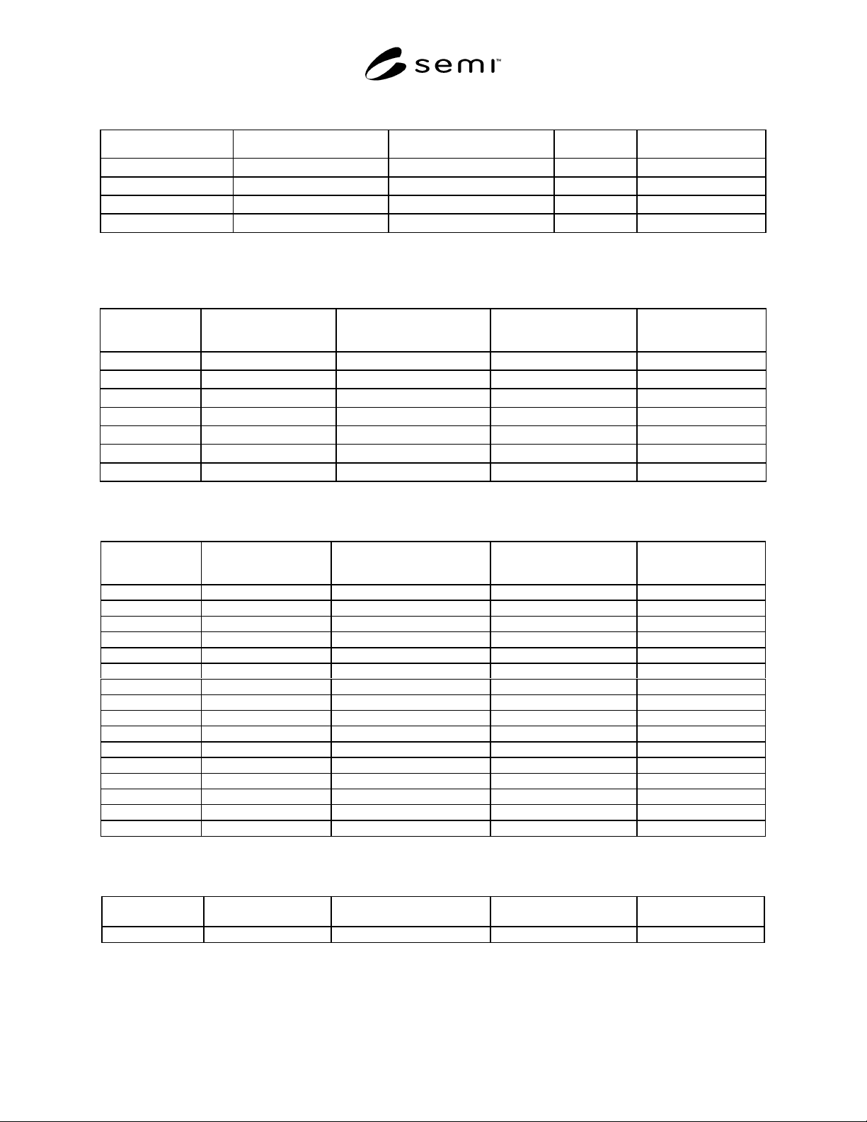
SEMI F57-0301 © SEMI 2000, 20015
Table 2 Particle Contribution Requirements
Description Qualification Test Method Units Value Notes
Rinse Time Test TBD Hours TBD Section 7.2
Initial Cycle Test TBD *Particles/liter ≥ 0.1 µm TBD Section 7.2
2000 Cycle Test TBD *Particles/liter ≥ 0.1 µm TBD Section 7.2
200,000 Cycle Test TBD *Particles/liter ≥ 0.1 µm TBD Section 7.2
* Cycle Test values are a result of subtracting the pre-cycle test background average. See Section 7.2.6.
TBD = To be determined (see NOTE 1 under Table 1).
Table 3 Surface Extractable Ionic Contamination Requirements
Description Component
Preparation Practice
Qualification Test Method Static Value at 85 ± 5°C
for 7 days (µg/m
2
)
Notes
Bromide SEMI F40 ASTM D4327 ≤ 100 Section 7.3
Chloride SEMI F40 ASTM D4327 ≤ 3000 Section 7.3
Fluoride SEMI F40 ASTM D4327 ≤ 60,000 Section 7.3
Nitrate SEMI F40 ASTM D4327 ≤ 100 Section 7.3
Nitrite SEMI F40 ASTM D4327 ≤ 100 Section 7.3
Phosphate SEMI F40 ASTM D4327 ≤ 300 Section 7.3
Sulfate SEMI F40 ASTM D4327 ≤ 300 Section 7.3
NOTE 1: Optional testing may be required by the end user for ammonium.
Table 4 Surface Extractable Metallic Contamination Requirements
Description Component
Preparation Practice
Qualification Test Method Static Value at 85 ± 5°C
for 7 days (µg/m
2
)
Notes
Aluminum SEMI F40 (See NOTE 1.) ≤ 10 Section 7.4
Barium SEMI F40 (See NOTE 1.) ≤ 15 Section 7.4
Boron SEMI F40 (See NOTE 1.) ≤ 10 Section 7.4
Calcium SEMI F40 (See NOTE 1.) ≤ 30 Section 7.4
Chromium SEMI F40 (See NOTE 1.) ≤ 1 Section 7.4
Copper SEMI F40 (See NOTE 1.) ≤ 15 Section 7.4
Iron SEMI F40 (See NOTE 1.) ≤ 5 Section 7.4
Lead SEMI F40 (See NOTE 1.) ≤ 1 Section 7.4
Lithium SEMI F40 (See NOTE 1.) ≤ 2 Section 7.4
Magnesium SEMI F40 (See NOTE 1.) ≤ 5 Section 7.4
Manganese SEMI F40 (See NOTE 1.) ≤ 5 Section 7.4
Nickel SEMI F40 (See NOTE 1.) ≤ 1 Section 7.4
Potassium SEMI F40 (See NOTE 1.) ≤ 15 Section 7.4
Sodium SEMI F40 (See NOTE 1.) ≤ 15 Section 7.4
Strontium SEMI F40 (See NOTE 1.) ≤ 0.5 Section 7.4
Zinc SEMI F40 (See NOTE 1.) ≤ 10 Section 7.4
NOTE 1: See Related Documents Section 12.5 for an applicable leachable trace inorganics test method.
Table 5 Surface Extractable Total Organic Carbon (TOC) Contamination Requirements
Description Component
Preparation Practice
Qualification Test Method Static Value at 85 ± 5°C
for 7 days (µg/m
2
)
Notes
TOC SEMI F40 ASTM D4779 or D5904 ≤ 60,000 Section 7.5