semi合集-English.pdf - 第1044页
SEMI E4-0699 © SE MI 1980, 1999 6 any ca se wh en an N AK is sent, the receiv er may dis- card any data it h as recei ved f or the block. The receiver returns immediately to the Idle state after se nding an ACK or NAK. 5…

SEMI E4-0699 © SEMI 1980, 19995
5.4 Retry Limit, RTY — The retry limit, RTY, is the
maximum number of times the Block Transfer Protocol
will attempt to retry sending a block before declaring a
failed send. (See Section 5.8.2.)
5.5 Master/Slave — The master/slave parameter is
used in the resolution of contention (see Section 5.8.2).
The host is designated as the slave. The equipment is
desig-nated as the master. This convention is based
upon the assumption that the equipment is less able to
store messages than the host.
5.6 Block Lengths — The unsigne d integer value of
the first byte sent after receipt of EOT is the length of
the block being sent. The length includes all the bytes
sent after the length byte, excluding the 2 bytes of the
checksum. The maximum block length allowed by
SECS-I is 254 bytes, and the minimum is 10 bytes.
5.7 Checksum — The checksum is calculated as the
numeric sum of the unsigned binary values of all the
bytes after the length byte and before the checksum in a
single block. The checksum is sent as 16 bits in two
bytes following the last byte of the block data. The high
order eight bits of the checksum will be sent first,
followed by the low order eight bits. The checksum is
used by the receiver to check for transmission errors.
The receiver performs the same checksum calculation
on the received header and data.
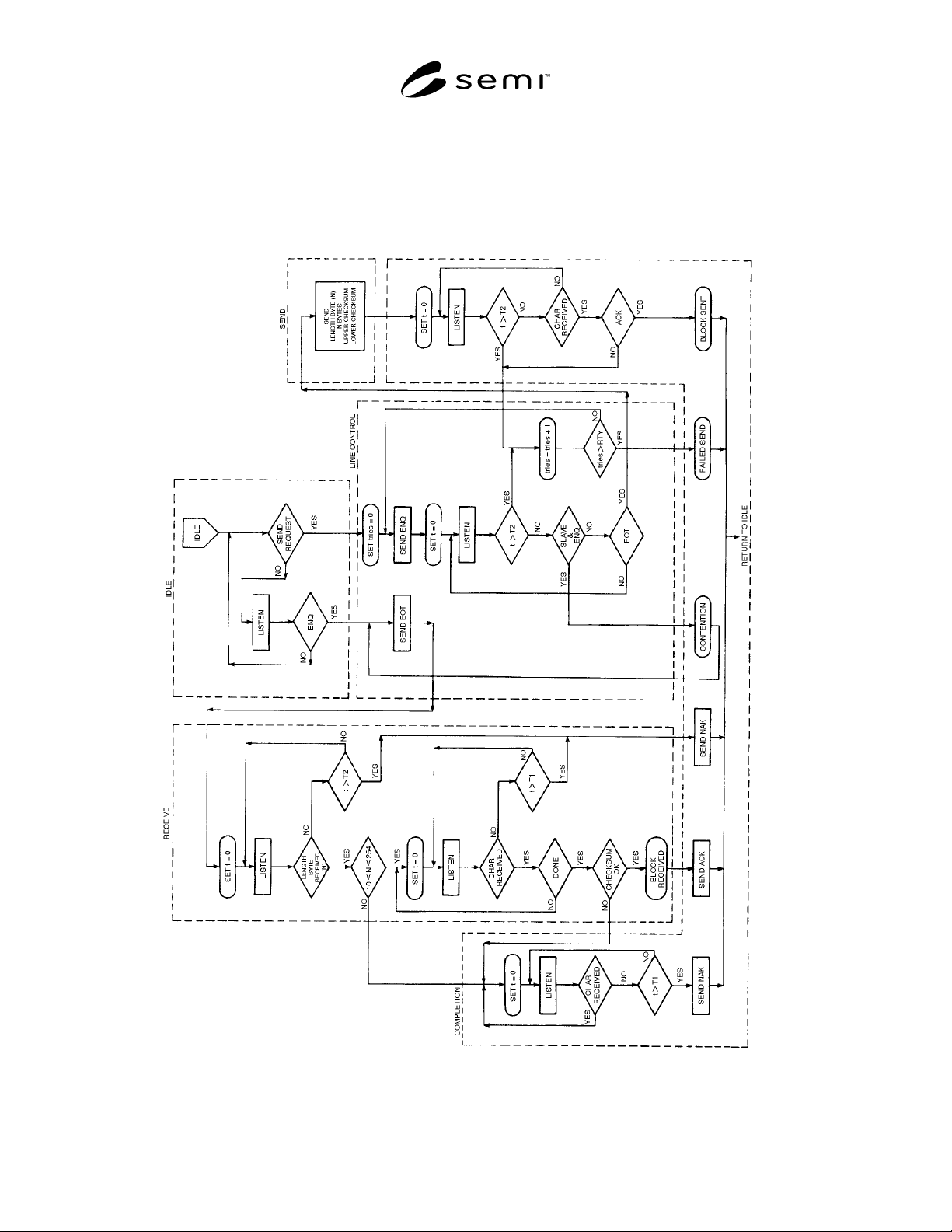
5.8 Algorithm — The operation of the block transfer
protocol is best understood by following the logic flow
in Figure 2. This flow chart depicts the operation of the
five states of the protocol - Receive, Idle, Send Line
Control, and Completion. The flow chart shown in Fig-
ure 2 is not meant to imply that a particular implemen-
tation is required under this standard. However, any
SECS-I block transfer protocol implementation must in-
clude all the logic described in Figure 2. The same
algorithm is executed on each end of the SECS-I
communications link.
5.8.1 Idle State — Both ends of the communications
link are assumed to start in the Idle state. There are two
primary activities of the protocol signified by the two
exits from the Idle state. These are:
A. SEND — a message block is to be sent.
B. RECEIVE — the other end of the communications
link has a message block to send
5.8.2 Line Control — The line control section estab-
lishes the transmission direction, resolves contention,
and handles retries. When an ENQ is received in the
Idle state, the Line Control responds with an EOT if the
Block Transfer Protocol is ready to receive. The Block
Transfer Protocol then goes to the Receive state. If a
message block is to be sent, then an ENQ is sent. If an
EOT is received in response to the ENQ within the time
limit T2, the Block Transfer Protocol goes to the Send
state.
5.8.2.1 If the slave receives an ENQ in response to the
ENQ, contention has occurred. The slave postpones the
send of its block until it receives a block from the
master. The slave prepares to receive the incoming
block and sends an EOT. When the block transfer
protocol returns to the Idle state, the postponed block
Send may be sent as if it were a new send request. After
a master sends an ENQ, it can ignore all characters
except an EOT. After a slave sends at ENQ, it can
ignore all characters except an ENQ or EOT.
5.8.2.2 When the time between sending ENQ and
receiving EOT exceeds T2, or the time between sending
the second checksum byte and receiving any character
exceeds T2, or a non-ACK character is received within
time T2 after sending the second checksum byte, the
Line Control will increment the retry count ("tries" in
the flowchart). If the retry count does not exceed the
value of the RTY parameter, then the Block Transfer
Protocol will retry sending the block beginning with
ENQ. If the retry count does exceed the value of the
RTY parameter, then a failed send has occurred.
5.8.3 Send — Once a send state is established, the first
byte sent is the length, N, of the data in the block. After
N more bytes have been sent, the two bytes of the
checksum are sent. The sender computes the checksum
based on the data in the block and the block header, but
not the length byte. When the sender receives the ACK
before time T2, the block is deemed properly sent.
However, if the sender receives a non-ACK character
before time T2, or no character within time T2, it
returns to the line control state for a possible retry. In
the Send state, characters received prior to sending the
last checksum byte can be ignored.
5.8.4 Receive — Once a receive state is established,
the first byte received is the length byte, N. The
receiver counts and saves the following N + 2 bytes.
The last two bytes are the checksum. The receiver
compares the two checksum bytes against its own
computation of the checksum. In a good block, the
computed and received checksum are the same.
5.8.5 Receive Completion — After a block is correctly
received, an ACK character is sent and the message
protocol is notified that a block has been received. If T2
is exceeded while waiting for the length character, or Tl
is exceeded between characters being received, then an
NAK is sent. If the length byte is invalid or if the re-
ceived checksum does not agree with the computed
checksum, the receiver continues to listen for characters
to ensure that the sender is finished sending. This is
detected when the inter-character time exceeds T1, at
which point the receive is aborted and a NAK is sent. In
SEMI E4-0699 © SEMI 1980, 1999 6
any case when an NAK is sent, the receiver may dis-
card any data it has received for the block. The receiver
returns immediately to the Idle state after sending an
ACK or NAK.
5.8.6 Send Completion — After the second checksum
byte is sent, if an ACK is received within time T2, the
message protocol is notified that the send was success-
ful. If a failed send occurs, the message protocol is in-
formed of the failure. Application-level software must
take the possibility of a send failure into account.
Figure 2
Block Transfer Protocol
SEMI E4-0699 © SEMI 1980, 19997
6 Header Structure
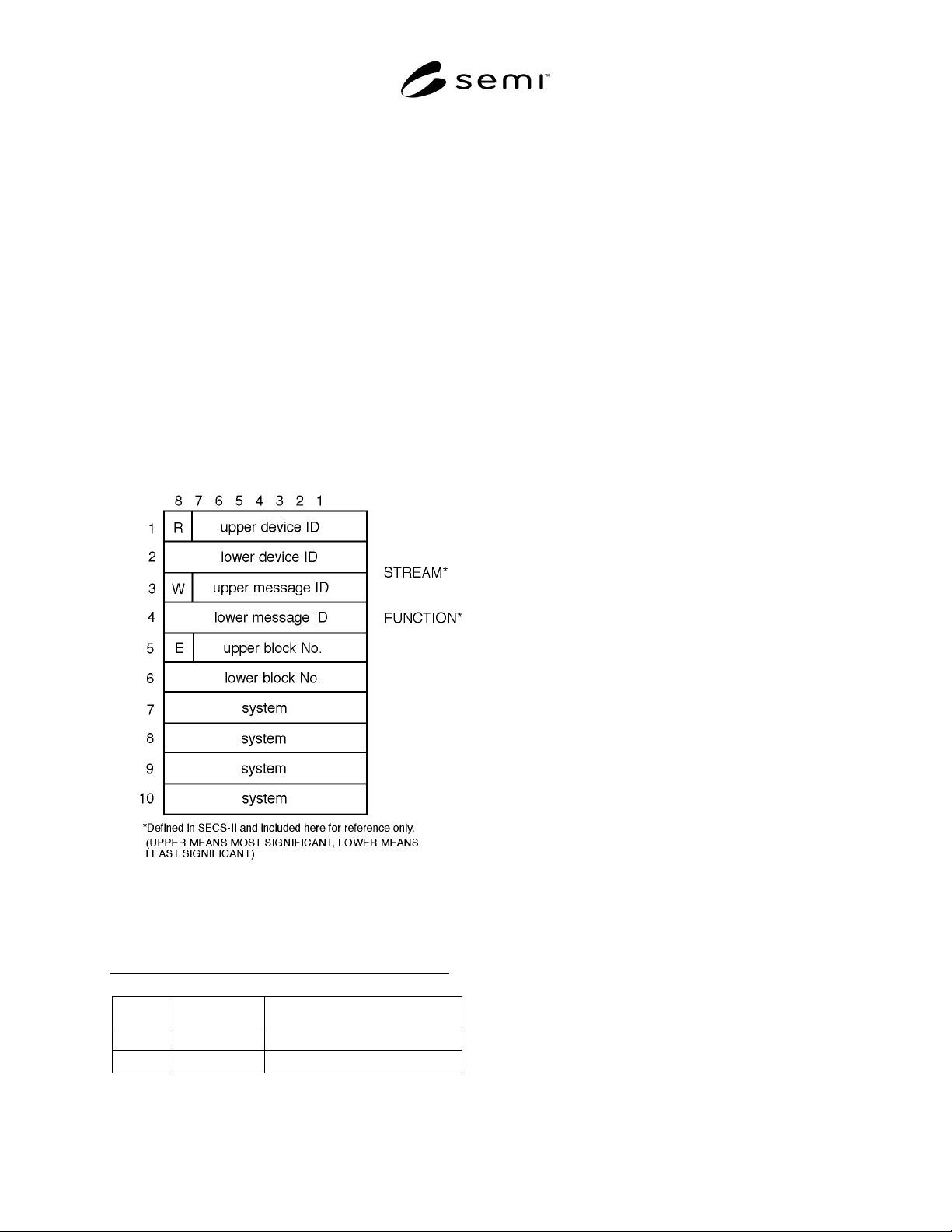
6.1 The operation of all communications functions
above the block transfer protocol is linked to
information contained in a 10-byte data element called
the header. The header is always the first 10 bytes of
every block sent by the block transfer protocol. The
information in the header is also used by the message
protocol (see Section 7). The fixed format of the header
is described in this section. The general header structure
is shown in Figure 3.
NOTE: The header also contains information required by
SECS-II.
6.2 Reverse Bit (R-Bit) — The reverse bit (R-bit)
signifies the direction of a message. The R-bit is set to 0
for messages to the equipment and set to 1 for messages
to the host. The R-bit is included in the header so that
the direction of the message is contained in every block.
Figure 3
Block Header Structure
Table 3 Influence of the R-BIT
R-Bit Device ID Message Direction
0 Destination Host to Equipment
1 Source Equipment to Host
6.3 Device ID — The device ID defines the source or
destination of the message depending upon the value of
the R-bit as shown in Table 3. Device identification is a
property of the equipment and must be settable
according to Section 8. The host can view the device ID
as a logical identifier connected with a physical device
within the equipment. The host has no device ID.
6.4 Wait Bit (W-Bit) — The wait bit (W-bit) is used to
indicate that the sender of a primary message expects a
reply. A value of one in the W-bit means that a reply is
expected. A value of zero in the W-bit means that no
reply is expected. The W-bit must be set to zero in all
secondary messages. For multi-block messages, the
sender must ensure that the W-bit is the same in every
block of the message.
6.5 Message ID — The message ID identifies the
format and content of the message being sent (the
particular message is one of many possible for the
device in question). The exact message content is
equipment-dependent. The upper message ID is the
most significant portion of the ID.
6.5.1 Primary Message — A primar y message is
defined as any odd numbered message. An odd
numbered message will have bit 1 of the lower message
ID set to 1.
6.5.2 Secondary Message — A secondary message is
defined as any even numbered message. An even-
numbered message will have bit 1 of the lower message
ID set to 0.
NOTE: In SECS-II, byte three of the header (excluding the
W-bit) is known as the stream, and byte four of the header is
known as the function. See SECS-II for more information.
6.6 End Bit (E-Bit) — The end bit (E-bit) is used to
determine if a block is the last block of a message. A
value of one in the E-bit means that the block is the last
block. A value of zero means that more blocks are to
follow.
6.7 Block Number — A message sent as more than
one block is called a multi-block message. The first
block is given a block number of one, and the block
number is incremented by one for each subsequent
block until the entire message is sent. The blocks of a
multi-block message are sent in order. In a single-block
message, the block number must have a value of zero or
one. The maximum block number is 32,767. The upper
block number is the most significant portion of the
block number. (See also 7.2.)
6.8 System Bytes — The system bytes in the header of
each message for a given device ID must satisfy the
following requirements. (For a further discussion of
system bytes, see Related Information R1-5.)