semi合集-English.pdf - 第913页
SEMI E118-1104 E © SEMI 2002, 2004 7 9.2.2 Table 3 defi nes the states of the WIDR. Definitions a re in alphabetical order . Table 3 WIDR Subsystem State Defi nitions State Definition ALARM STATUS Shows the presence or a…
SEMI E118-1104
E
© SEMI 2002, 2004 6
8.3.2 In the case of multiple heads, it must be possible to distinguish between the attributes of different heads.
Table 2 Reader Head Attribute Definitions
Attribute Name Description Access Reqd Form
Fundamental
HeadStatus The current state. RO Y Enumerated:
IDLE
BUSY
NOT OPERATING
HeadID Head number 0–31. RO Y if
multi-head
Text. 2 digits.
Optional
HeadCondition The current Maintenance status. RO N Enumerated:
No alarms
Needs Maintenance
Read fault
HeadDateInstalled Date this head was installed. RO N Protocol dependent.
HeadMaintenance-Data Supplier dependent. RO N Text
9 State Models
9.1 To facilitate independent control of the individual heads, this section defines two separate state models, one for
WIDR subsystem and one to be applied to each of the individual heads.
9.2 WIDR State Model
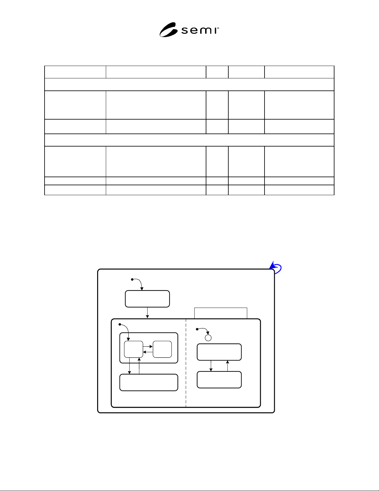
9.2.1 This section defines the state model for the WIDR subsystem. Figure 1 shows the diagram for this model.
1
WIDR
INITIALIZING
OPERATING
3
2
NO ALARMS
A
LARMS
C
MAINTENANCE
4
5
9 10
A
LARM STATUS
OPERATIONAL STATUS
RUNNING
11
IDLE
7
8
6
BUSY
Figure 1
WIDR State Model Diagram
SEMI E118-1104
E
© SEMI 2002, 2004 7
9.2.2 Table 3 defines the states of the WIDR. Definitions are in alphabetical order.
Table 3 WIDR Subsystem State Definitions
State Definition
ALARM STATUS Shows the presence or absence of alarms.
ALARMS An alarm condition exists.
BUSY A service is being performed that affects the state of the hardware.
WIDR Superstate of WIDR State Model. Always active when WIDR powered on.
IDLE No service is being performed. All heads are idle.
INITIALIZING WIDR is performing initialization and self diagnostics. Presence or absence of alarms is
initially determined in this state.
NO ALARMS No alarm conditions exist.
OPERATING Normal operational states where reading operations can be performed.
OPERATIONAL STATUS The WIDR is fully capable of performing all services that it supports.
RUNNING The WIDR is operational and able to communicate.
MAINTENANCE Internal setup and maintenance activities.
9.2.3 Table 4 defines the transitions of the WIDR State Model.
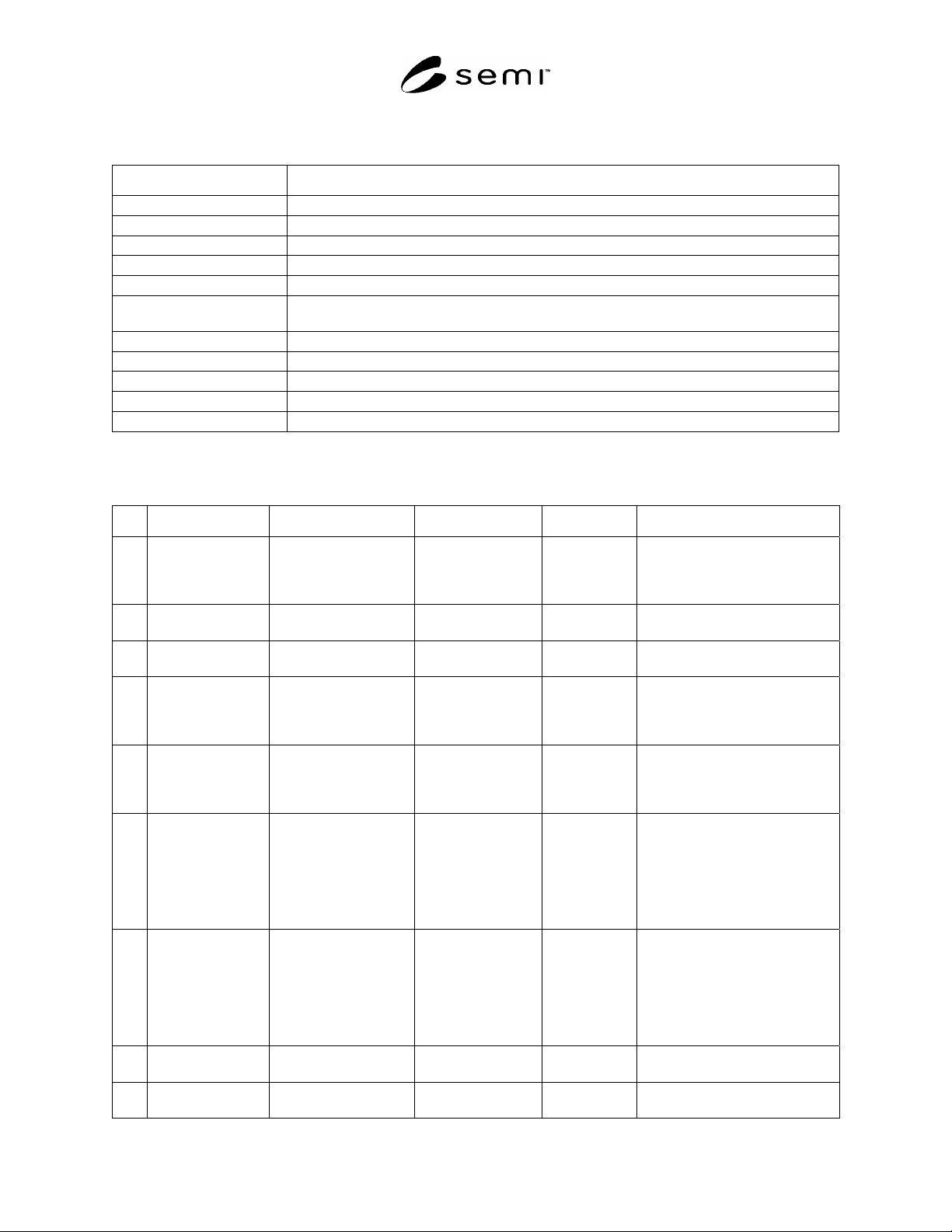
Table 4 WIDR State Transitions
# Previous State Trigger New State Actions Comments
1 (Any) Power-up or reset. INITIALIZING Initialize
hardware
and software
components.
Default entry on power-up.
2 INITIALIZING Initialization is
complete.
RUNNING None The WIDR is now able to
communicate.
3 INITIALIZING Default entry into
OPERATING.
IDLE None Internal
4 IDLE A service request to
read or perform
diagnostics is
received.
BUSY None
5 BUSY All service requests
that affect the state of
the hardware are
completed.
IDLE None
6 IDLE A user selects the
MAINTENANCE
state and all heads are
idle.
MAINTENANCE None The upstream controller may
send a request or the operator
may set a switch to select the
OPERATING or the
MAINTENANCE state.
Maintenance and setup activities
may now be performed.
7 MAINTENANCE A user selects the
OPERATING state
and all heads are idle.
IDLE None The upstream controller may
send a request or the operator
may set a switch to select the
OPERATING or the
MAINTENANCE state. Normal
operating activities may now be
performed.
8 INITIALIZING Default entry into
ALARM STATUS.
ALARMS or NO
ALARMS
None
9 NO ALARMS An alarm condition is
detected.
ALARMS None
SEMI E118-1104
E
© SEMI 2002, 2004 8
# Previous State Trigger New State Actions Comments
10 ALARMS All alarm conditions
have cleared.
NO ALARMS None
11 Any A reset service
request is received.
WIDR None
9.3 Read Head State Model
9.3.1 For a WIDR with multiple heads, this state model shall be provided for each Read Head.
9.3.2 For the single head case, these states are covered in the WIDR state model and no additional state model for
the head is required. IDLE and BUSY correspond to substates of the same names in the WIDR state model. If any
head is NOT OPERATING, then the active substate of ALARM STATUS in the WIDR state model is ALARMS.
9.3.3 The NOT OPERATING state is not required, if it is not possible to detect alarms related to the head. Note
also that some alarm conditions are fatal (so that the head cannot operate with full functionality) while others may
not be fatal.
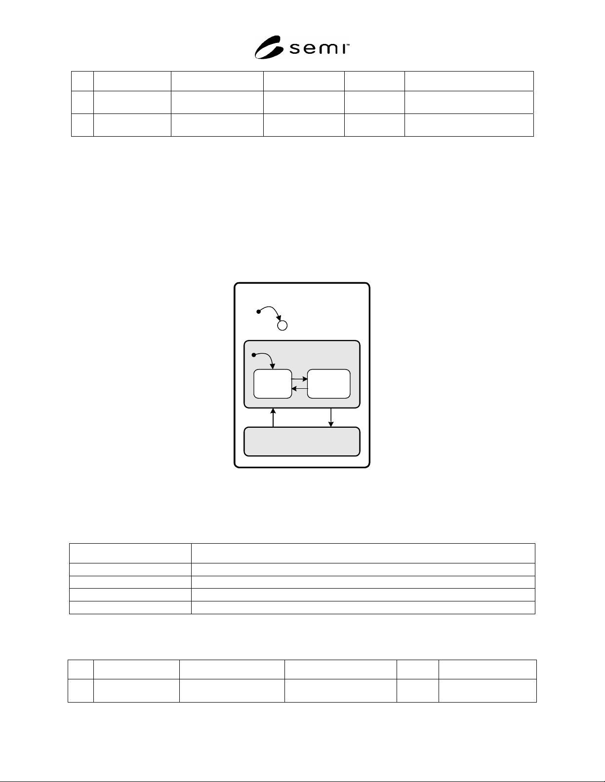
9.3.4 Figure 2 shows the diagram for the Read Head State Model.
WIDR HEAD
C
12
OPERATING
1
6
BUSYIDLE
13
14
15
NOT OPERATING
Figure 2
Read Head State Model
9.3.5 Table 5 defines the states for the Read Head.
Table 5 Read Head State Definitions
State Definition
NOT OPERATING Head is in a non-operational state or has reduced functionality. Maintenance is required.
OPERATING Head is active and fully functional.
IDLE Head is not performing a service.
BUSY Head is performing a service.
9.3.6 Table 6 defines the transitions of the Read Head State Model.
Table 6 Read Head State Transitions
# Previous State Trigger New State Actions Comments
12 (unknown) Initialization on power-up
or reset.
Either NOT OPERATING
or OPERATING.
None Default entry on
power-up.