semi合集-English.pdf - 第1615页
SEMI E38-1296 © SEMI 1995 , 1996 4 4.1.49 t ransfer res ource — a modu le r es ource within a transport module i ndependen tly capable of transferring material from one attached module to another. 4.2 Data Type 4.2.1 for…

SEMI E38-1296 © SEMI 1995, 19963
4.1.21 interface flange — the boundary plane
separating an attached module and a single transport
module.
4.1.22 intertool environment — defined relative to a
particular cluster tool to be everywhere outside of the
intratool environment.
4.1.23 intertool material transfer job — a transfer job
in the cluster controller to receive material from, or
send the material to, the factory. In automated transfer,
it may be an element of a factory transfer job.
4.1.24 intertool port resource — a module resource
associated with a particular cassette module which
operates on behalf of the said module during material
transfer between the cassette module and the intertool
environment.
4.1.25 intratool environment — the entire
environmentally isolated volume contained within a
cluster tool.
4.1.26 intratool port resource — a module resource
associated with a particular interface plane of a
particular attached module which operates on behalf of
the said module during material transfer between the
transport module and the attached module.
4.1.27 intratool material transfer job — a transfer job
in a cluster controller for transfer of material from one
attached module to another through the linking
transport module.
4.1.28 isolation valve — a mechanical component
used at an interface plane to permit environmental
isolation between the transport module and an attached
module.
4.1.29 material handoff — the process by which
material moves from the sending transfer partner to the
receiving transfer partner.
4.1.30 material location — a physical position capable
of holding a single material.
4.1.31 material slot — a material location in a carrier
capable of holding a single material with an assigned
identifier.
4.1.32 module — an independently operable unit that
is part of a tool or system. [SEMI E21]
4.1.33 module resource — an entity which provides
specific capabilities required of the module to be
accessed or controlled externally. This includes the
physical capability and the associated control and
access management. It may contain material in one or
more material locations.
4.1.34 namespace — a domain within which object
identifiers are unique.
4.1.35 port — a point on the cluster at which a change
of ownership of material occurs. A port is not itself a
location but must have an associated location, such as
an interface plane.
4.1.36 process job — a material processing job for a
process module, specifying and tracking the processing
to be applied to the material while in the module.
4.1.37 process module — an attached module which
provides manufacturing value to material in a cluster
tool.
4.1.38 processing resource — a module resource
within a module which is independently capable of
providing manufacturing value to material.
4.1.39 protocol (communications) — the message
encoding used when transferring a message across
some communication facility.
4.1.40 recipe — the pre-planned and reusable portion
of the set of instructions, settings, and parameters under
control of a processing agent that determines the
processing environment seen by the material. Recipes
may be subject to change between runs or processing
cycles.
4.1.41 recipe executor — a component of a module
that stores and executes recipes.
4.1.42 recipe namespace — a logical management
domain with the responsibility for the storage and
management of recipes. It ensures the uniqueness of
recipe identifiers and provides services pertaining to
recipes stored within that domain.
4.1.43 recovery action — an operation associated with
an error condition with the aim of resolving the
abnormal situation detected. It may supply information
to the exception agent or request the exception agent to
perform some activity.
4.1.44 service — the set of messages and definition of
the behavior of a service provider that enables remote
access to a particular functionality.
4.1.45 service-provider — the software control entity
that is the provider of any of the related services.
4.1.46 service-user — the software control entity that
is the user of any of the related services.
4.1.47 transport module — a module containing one
or more transfer resources and a number of interface
planes. It is capable of end-to-end transfer between any
of the interface planes.
4.1.48 tm transfer job — a material transfer job for a
transport module specifying all criteria for receiving the
material from the source-attached module and sending
the material to the destination module.

SEMI E38-1296 © SEMI 1995, 1996 4
4.1.49 transfer resource — a module resource within a
transport module independently capable of transferring
material from one attached module to another.
4.2 Data Type
4.2.1 form — type of data: positive integer, unsigned
integer, integer, enumerated, boolean, text, formatted
text, structure, list, ordered list.
4.2.2 positive integer — may take the value of any
positive whole number. Messaging protocol may
impose a limit on the range of possible values.
4.2.3 unsigned integer — may take the value of any
positive integer or zero. Messaging protocol may
impose a limit on the range of possible values.
4.2.4 integer — may take on the value of any negative
or unsigned integer. Messaging protocol may impose a
limit on the range of possible values.
4.2.5 enumerated — may take on one of a limited set
of possible values. These values may be given logical
names, but they may be represented by any single-item
data type.
4.2.6 boolean — may assume one of two possible
values, equating to TRUE or FALSE.
4.2.7 text — a text string. Messaging protocol may
impose restrictions, such as length or ASCII
representation.
4.2.8 formatted text — a text string with an imposed
format. This could be by position, by use of special
characters, or both.
4.2.9 structure — a complex structure consisting of a
specific set of items, of possibly mixed data types, in a
specified arrangement.
4.2.10 list — a set of one or more items that are all of
the same form (one of the above forms).
4.2.11 ordered list — a list for which the order in
which items appear is significant.
5 Conventions
5.1 Harel State Model
5.1.1 This document uses the Harel State Chart
notation to describe the dynamic behavior of the objects
defined. An overview of this notation is presented in an
Appendix of SEMI E30. The formal definition of this
notation is presented in Science of Computer
Programming 8, “Statecharts: A Visual Formalism for
Complex Systems,” by D. Harel, 1987.
5.1.2 Transition tables are provided in conjunction
with the state diagrams to describe explicitly the nature
of each state transition. A transition contains columns
for Transition #, Current State, Trigger, New State,
Action(s). The “trigger” (column 3) for the transition
occurs while in the “current” state. The “actions”
(column 5) include a combination of (1) actions taken
upon exit of the current state, (2) actions taken upon
entry of the new state, and (3) actions taken which are
most closely associated with the transition. No
differentiation is made.
5.2 OMT Object Information Model — The object
models are presented using the Object Modeling
Technique developed by Rumbaugh, James, et al., in
“Object-Oriented Modeling and Design,” Prentice Hall,
Englewood Cliffs, NJ, ©1991. Overviews of this
notation are provided in an appendix to SEMI E39.
5.3 Object Attribute Representation — The object
information models for standardized objects will be
supported by an attribute definition table with the
following column headings:
Attibute Name Definition Access Rqmt Form
The formal
text name of
the attribute.
Description of
the
information
contained.
RO or RW Y or N (see
below)
The Access column uses RO (Read Only) or RW (Read
and Write) to indicate the access that service-users have
to the attribute.
A ‘Y’ or ‘N’ in the requirement (Rqmt) column
indicates if this attribute must be supported in order to
meet fundamental compliance for the service.
The Form column is used to indicate the format of the
attribute. (See Section 4.1 for definitions.)
6 Overview
The Cluster Tool Module Communications standard
specifies the communications services necessary to
achieve automated control within a cluster tool. It
defines the essential cluster tool architecture and the
concepts and models on which the communications
services are based.
Cluster tools provide a means of grouping a number of
independent process steps into a single equipment. The
primary function of a cluster tool is material processing.
Material enters the cluster tool, undergoes a number of
sequential process steps which adds value to the
material, and then exits.
SEMI E38-1296 © SEMI 1995, 19965
From a mechanical viewpoint, Cluster Tool Module Interface standards-compliant equipment has a physical
structure where process modules and cassette modules are attached in a standardized way to some form of transport
module, a robotic material handler operating in an isolated environment. Cassette modules provide the input and
output of material for the cluster tool, usually in cassettes.
This communications standard enables the distributed control of these cluster tools, and of other cluster tools and
multi-resource equipment which can be decomposed into process, transport, and cassette modules, whether
environmentally isolated or not. A basic assumption is made that the primary human-machine interfaces are not
located at the individual modules.
Communication and control services are specified among service-users and service-providers within a cluster tool.
The service-providers are the controlled processing, transfer, intratool port, and intertool port resources in the
appropriate modules. The service-users are the application entities responsible for supervisory control and data
acquisition within the cluster tool.
The services are fully defined in terms of the service-providers, and as such, do not dictate the architecture of the
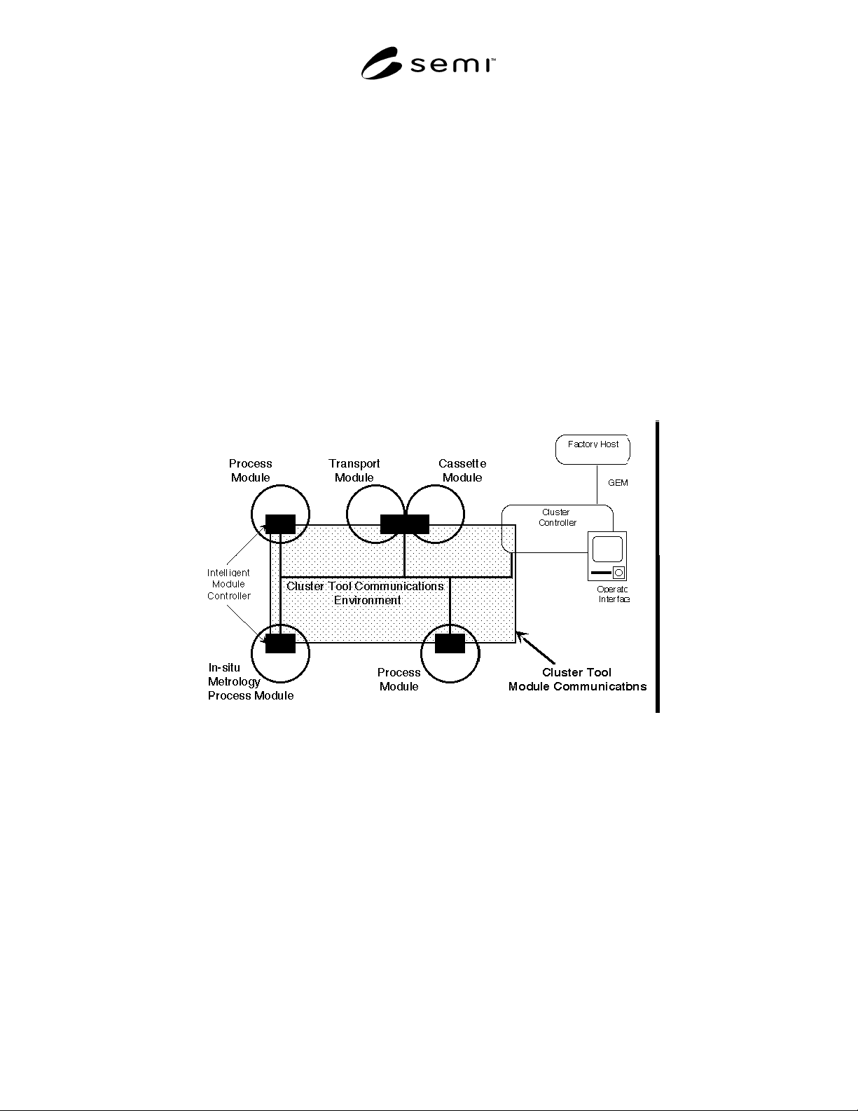
service-user(s). An example of cluster tool control architecture is shown in Figure 1, where the service-user is a
single cluster controller platform providing internal scheduling, human-machine interface, and standardized
communications interface to the factory.
Figure 1
Example Cluster Control Architecture
The communication services include primary control services for material processing in process modules
(processing management) and material movement within the cluster tool and material input/output with the factory
(material movement management). The cluster controller, which is responsible for supervisory control within the
cluster tool, is the service-user of these primary control services. The form of the cluster controller is not dictated. It
may be a single platform, distributed, or incorporated with one or more modules.
Support services are also specified to enable resolution of exception conditions, recipe handling, event reporting and
data access. The decision authority, which is responsible for making error recovery decisions, is the service-user for
exception management. Appropriate agents are the designated service-users for the recipe management and event
reporting support services. All service-users access data using the Object Services.
The communications services are defined independently of protocol in order to allow future standardization of
alternative protocols without invalidating the services. Figure 2 shows the full communications stack needed for
compliance, where the services are mapped to the communications environment, which is defined in supplementary
standards.