semi合集-English.pdf - 第534页
SEMI E77-1104 © SEMI 1998, 2004 2 5.2.8 nameplate ga s — the gas intended to be controlled by the MFC in operat ion. 5.2.9 range — the algebraic difference between the maximum and minimum values. 5.2.10 setpoint — the in…

SEMI E77-1104 © SEMI 1998, 2004 1
SEMI E77-1104
TEST METHOD FOR CALCULATION OF CONVERSION FACTORS FOR
A MASS FLOW CONTROLLER USING SURROGATE GASES
This test method was technically approved by the Global Gases Committee and is the direct responsibility of
the North American Gases Committee. Current edition approved by the North American Regional Standards
Committee on July 11, 2004. Initially available at www.semi.org September 2004; to be published
November 2004. Originally published September 1998.
1 Purpose
1.1 The purpose of this test method is to quantify a
nominal average conversion factor from one gas to
another for an MFC and to quantify the conversion
factor as function of flow for an MFC.
2 Scope
2.1 This procedure describes a method to determine the
MFC conversion factor and function between two
gases.
2.2 This document provides a common basis for
communication between manufacturers and users.
2.3 The intent of this document is not to suggest any
specific testing program, but to specify the test method
to be used when testing for parameters covered by this
method. Reference operating conditions represent the
environmental conditions where the “best” performance
can be expected.
NOTICE: This standard does not purport to address
safety issues, if any, associated with its use. It is the
responsibility of the users of this standard to establish
appropriate safety and health practices and determine
the applicability of regulatory or other limitations prior
to use.
3 Limitations
3.1 It is not practical to evaluate performance under all
possible combinations of operating conditions. This
test procedure should be applied under laboratory
(reference) conditions; its intent is to collect sufficient
data to form a judgment of the field performance of the
MFC being tested.
3.1.1 The results from this test represent the
performance of the specific device tested (i.e., make,
model, full scale flow and operating conditions). The
results may not apply to devices of different
manufacture, model, full scale flow or under different
operating conditions.
3.2 This procedure does not apply to pressure based
MFC.
4 Referenced Standard
4.1 None.
NOTICE: Unless otherwise indicated, all documents
cited shall be the latest published versions.
5 Terminology
5.1 Abbreviations & Acronyms
5.1.1 CF (gasA/gasB) — conversion factor from Gas A
to Gas B.
5.1.2 D.U.T.— device under test
5.1.3 kPa — kiloPascal
5.1.4 MFC — mass flow controller
5.1.5 psia — pounds per square inch absolute
5.1.6 sccm — standard cubic centimeters per minute
5.1.7 slm — standard liters per minute
5.1.8 %F.S. — percent full scale
5.2 Definitions
5.2.1
actual flow — the flow rate as determined by the
flow standard used in the test procedure.
5.2.2 conversion factor — the ratio of the mass flow-
rate of Gas A flowing through an MFC for a given
setpoint to the mass flow rate of Gas B flowing through
the same MFC and setpoint.
5.2.3 conversion function — a relationship that
describes the flow dependency of the conversion factor.
The conversion function is graphically determined.
5.2.4 indicated flow — the flow rate as determined by
the output of the D.U.T.
5.2.5 mean — the sum of a group of measurements
divided by the number of measurements; average.
5.2.6 measured value — the actual flow through a
D.U.T., expressed in sccm or slm.
5.2.7 measured value, average — the sum of all
readings (both upscale and downscale) for all cycles, at
a single setpoint, divided by the number of these
readings.

SEMI E77-1104 © SEMI 1998, 2004 2
5.2.8 nameplate gas — the gas intended to be
controlled by the MFC in operation.
5.2.9 range — the algebraic difference between the
maximum and minimum values.
5.2.10 setpoint — the input signal provided to achieve
a desired flow, reported as sccm, slm, or percent full
scale.
5.2.11 span — the full scale range of the D.U.T.
5.2.12 surrogate gas — the gas substituted for the
nameplate gas during the calibration process.
5.2.13 zero drift — the undesired change in electrical
output (i.e., indicated flow), at a no-flow condition,
over a specified time period, reported in sccm or slm.
5.2.14 zero offset — the deviation from zero at a “no-
flow” condition reported in sccm, slm, or mV.
6 Summary of Test Method
6.1 Gas flow and setpoint data are collected for two
gases. This data is reduced to quantify the relationship
between the flow measurement by the MFC on one gas
to another gas.
6.2 This method allows the user to determine the
conversion factor between two gases for the MFC and
to determine the onset of errors in the MFC calibration
due to the conversion factor/function effects.
7 Interferences
7.1 The accuracy rating of the measuring equipment
shall be superior to that of the D.U.T. Preferably the
measuring equipment will have an accuracy that is four
times better than the D.U.T. Calibration equipment
must have a valid calibration certificate.
7.2 Take care when using test instruments with a
specified accuracy expressed in percent of full scale.
7.3 Installation effects on the flow should be
minimized. Monitor pressure upstream of the D.U.T.
to ensure that flow variations due to pressure are
minimized.
7.4 Verify electrical signals directly at the D.U.T.
connector to ensure that the signals at the D.U.T. and
standard agree with the signals at the data recording
equipment.
7.5 Certain gases will contaminate the D.U.T. This
test should be considered a destructive test in such
cases.
7.6 All electrical measurements should be read on
devices with at least 4.5 digits of resolution. These
devices must have valid calibration certifications.
7.7 The device mounting position must be in
accordance with the manufacturer’s specifications.
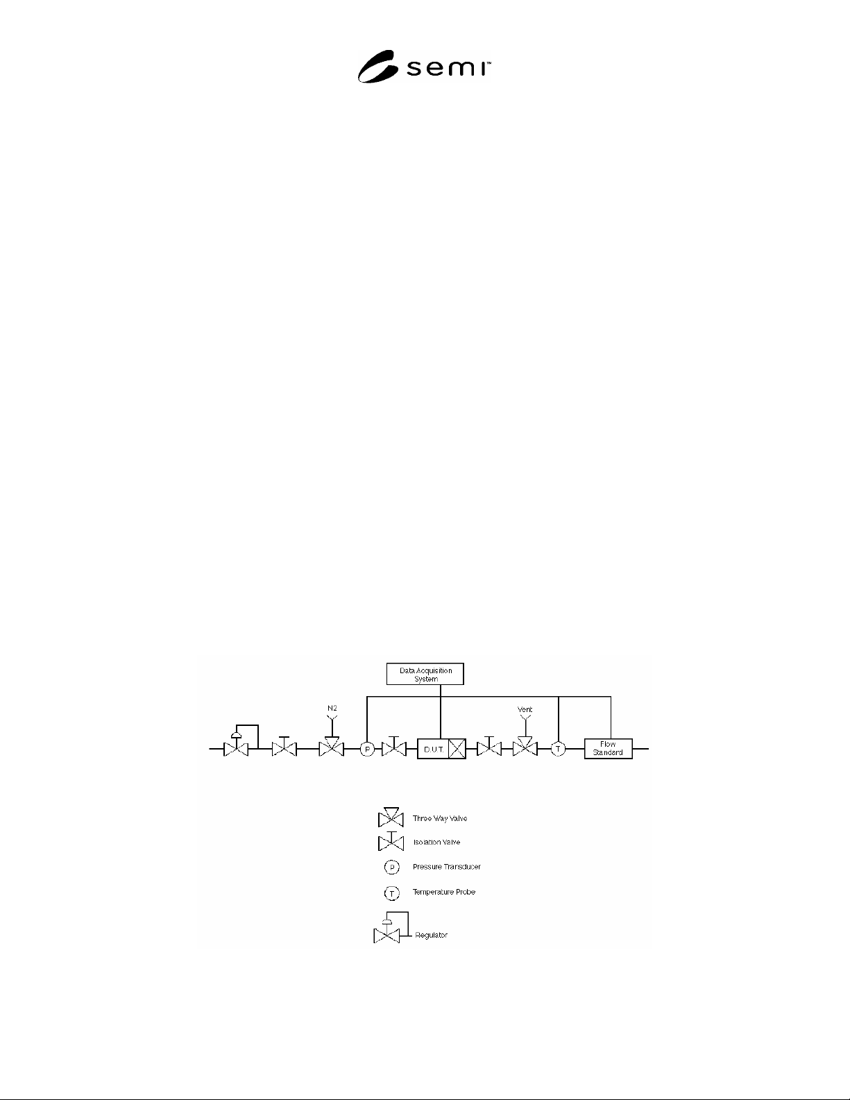
8 Apparatus (See Figure 1.)
8.1 Flow Standard — A device or system that
accurately measures the flow and reports the actual
flow.
8.2 Data Acquisition System — The system that
measures the electrical signals from the device under
test. The data acquisition system may also read the
signals from the flow standard, record test data and
control the test sequence.
8.3 Temperature Probe — A device to measure the
temperature of the flowing gas.
8.4 Three-Way Valve — A special valve to switch the
system from one gas source to another.
8.5 Manual Isolation Valves — Valves that will
positively shut off the gas line.
8.6 Pressure Regulator — A device that regulates gas
pressure to a set value.
8.7 Pressure Transducer — An instrument to measure
the gas pressure and report it as an electrical signal.
9 Materials
9.1 Clean, Dry N
2
— With 99.999% minimum purity,
to be used for purging.
9.2 Test Gas “A”
9.3 Test Gas “B”
10 Safety Precautions
10.1 This test method may involve hazardous
materials, operations, and equipment. This test method
does not purport to address the safety considerations
associated with its use. It is the responsibility of the
user to establish appropriate safety and health practices
and to determine the applicability of regulatory
limitations before using this method.
10.2 Follow the manufacturer’s specifications and
instructions for installation and operation whenever
possible. Note any exceptions in the test report.
11 Test Specimen
11.1 Allow all components in the test apparatus to
warm up following the manufacturer’s specification.
11.2 Take necessary steps when switching gases to
ensure that only the desired gas is in the D.U.T. and
flow standard at the time the test is performed.
SEMI E77-1104 © SEMI 1998, 2004 3
12 Preparation of Apparatus
12.1 Locate the D.U.T. in the test environment to
stabilize temperature for 24 hours prior to warm up.
12.2 The reference operating conditions shall be as
follows:
12.2.1 Ambient Temperature — 23 ± 2°C
12.2.2 Gas Temperature — Same as ambient. In the
case of a condensible gas, the gas temperature should
be maintained as a gradient, with highest temperature at
the outlet end of the test set up, and slightly reduced
temperatures back to the source. This will ensure that
condensing vapors do not accumulate in the test set up.
Gradient should simulate actual process parameters
where the MFC will be installed.
12.2.3 Ambient Pressure — 101.3 kPa (+ 4.7 or – 15.3
kPa)
12.2.4 Gas Pressure, Inlet — 172 ± 34 kPa unless the
gas is not capable of delivering this pressure, then
normal fab operating conditions should be observed.
12.2.5 Gas Pressure, Outlet — < 80 kPa
12.2.6 Relative Humidity — 40% ± 5%, non-
condensing (suggestion: record if outside this range)
12.2.7 Magnetic Field — 50 µT
12.2.8 Electromagnetic Field — 100 µV/m
12.2.9 Vibration — 0.5 m/s at 50 to 200 Hz
12.3 Following the conditioning period (See Section
12.1), warm up the device according to manufacturer’s
specifications.
12.4 Perform an adequate nitrogen purge to ensure all
previous gases and moisture have been removed from
the system. Prior to corrosive gas testing, a cyclic
pump and purge operation is recommended, alternately
backfilling with nitrogen, and evacuating the test
manifold.
12.5 Leak check the manifold, using available
methodologies to verify the test system leak integrity.
Introduce the test gas at a sufficient rate and time to
ensure the test apparatus is completely filled with the
test gas and only the test gas.
12.6 Record the zero offset with line pressure inside
the MFC to best simulate normal operating conditions.
Line pressure during testing is to be 170.30 kPa (24.7
psia) unless safety practices for the gas under test
dictate that a lower line pressure be used.
NOTE 1: In addition, if this test is performed on hazardous
gases, bleeding off gas pressure to obtain atmospheric
pressure inside the MFC may not be easy to do.
12.7 Command 100%, and establish flow, then close
the downstream isolation valve; then close the upstream
isolation valve (see Figure 1).
12.8 With both isolation valves closed, and a 100%
setpoint wait until the pressure drop across the MFC is
dissipated, ensuring a “no flow” condition through the
MFC. Dissipation of the pressure across the MFC is
indicated when the indicated flow drops to a steady
state value near zero.
12.9 After the electrical output signal has stabilized for
at least three minutes, record the MFC zero offset in
Table 1.
Figure 1
Mass Flow Controller Test Fixture