semi合集-English.pdf - 第3639页
SEMI E142-0705 © SEMI 2005 1 SEMI E142-0705 SPECIFICATION FOR SUBSTRATE MAPPING This specification was technically approved by the Globa l Information & Control Committee and is the direct responsibility of the North…
SEMI E139.1-0705 © SEMI 2005 14
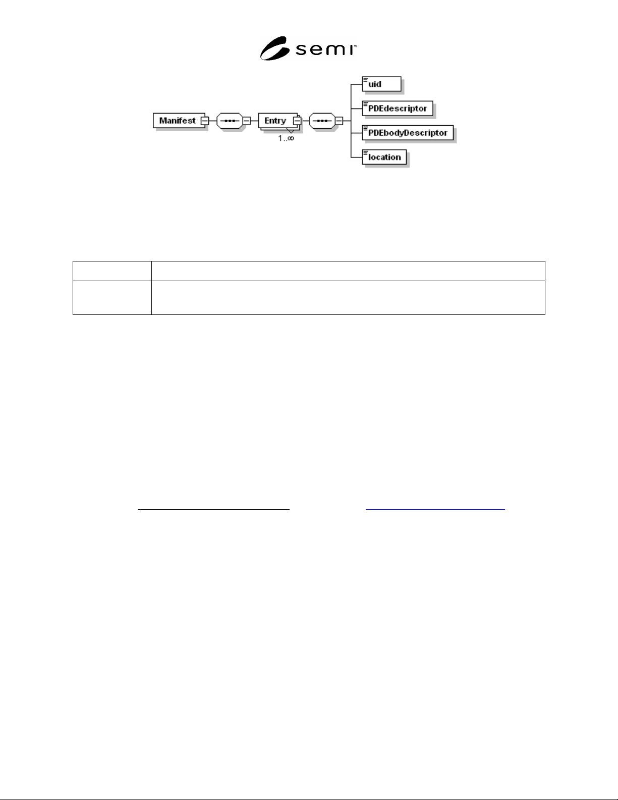
Figure 11
Manifest
8.1.3 XML simpleTypes
8.1.3.1 Table 11 describes each simpleType added to the XML schema for the Manifest.
Table 14 simpleTypes In The PDE Schema
Type Description
UUID Holds a standard 36-character uuid string. The pattern is defined as five groups of characters, each
separated by the “-“ character. Here is an example value in UUID format: “44BBA855-CC51-11CF-
AAFA-00AA00B6015C”.
8.2 Requirements For Manifest Schema
8.2.1 This section contains all requirements specified for the PDE Schema. ¶8.1 above is included for
documentation purposes.
8.2.2 All Manifest instance documents shall conform to the XML schema document named:
E139-1.V0705.RaP.Manifest.xsd
8.2.3 The contents of the above-mentioned schema document constitute a core part of this specification. This
schema document should be provided with this document.
8.2.4 In addition, all Manifest instance documents shall conform to all requirements related to the Manifest content
as specified in SEMI E139.
9 Related Documents
Rivest, Ronald, The MD5 Message-Digest Algorithm,
IETF RFC: 1992 http://www.ietf.org/rfc/rfc1321.txt.
NOTICE: SEMI makes no warranties or representations as to the suitability of the standards set forth herein for any
particular application. The determination of the suitability of the standard is solely the responsibility of the user.
Users are cautioned to refer to manufacturer's instructions, product labels, product data sheets, and other relevant
literature, respecting any materials or equipment mentioned herein. These standards are subject to change without
notice.
By publication of this standard, Semiconductor Equipment and Materials International (SEMI) takes no position
respecting the validity of any patent rights or copyrights asserted in connection with any items mentioned in this
standard. Users of this standard are expressly advised that determination of any such patent rights or copyrights, and
the risk of infringement of such rights are entirely their own responsibility.
Copyright by SEMI® (Semiconductor Equipment and Materials
International), 3081 Zanker Road, San Jose, CA 95134. Reproduction of
the contents in whole or in part is forbidden without express written
consent of SEMI.

SEMI E142-0705 © SEMI 2005 1
SEMI E142-0705
SPECIFICATION FOR SUBSTRATE MAPPING
This specification was technically approved by the Global Information & Control Committee and is the direct
responsibility of the North American Information & Control Committee. Current edition approved by the
North American Regional Standards Committee on December 10, 2004. Initially available at www.semi.org
January 2005; to be published March 2005.
NOTICE: The designation of SEMI M55 was updated during the 0705 publishing cycle to reflect the creation of
SEMI E142.1.
1 Purpose
1.1 This document defines the data items that are required to report, store and transmit map data for substrates such
as wafers, frames, strips and trays.
2 Scope
2.1 This version of the document applies to the substrate types; wafers, frames, strips and trays.
2.2 This document addresses assembly and packaging including the testing of semiconductor devices.
NOTICE: This standard does not purport to address safety issues, if any, associated with its use. It is the
responsibility of the users of this standard to establish appropriate safety and health practices and determine the
applicability of regulatory or other limitations prior to use.
3 Limitations
3.1 This document does not address the transmission, file naming conventions, storage or archiving of substrate
maps. These will be addressed in sub-documents of this specification.
4 Referenced Standards
4.1 SEMI Standards
SEMI E39 — Object Services Standard; Concept, Behavior and Services
NOTICE: Unless otherwise indicated, all documents cited shall be the latest published versions.
5 Terminology
5.1 Definitions
5.1.1 bottom side — the bottom side of the substrate as defined in the corresponding Appendix (Appendix 1, 2,
or 3).
5.1.2 device — the unit to which the device status code in the map is assigned including, but not limited to: die on a
wafer, multi-chip modules, and packages.
5.1.3 map — a two-dimensional array of bin codes derived from electrical test data of a substrate including, but not
limited to: wafer, tray, strip, or tape.
5.1.4 substrate — any carrier of a two-dimensional array of devices including, but not limited to: wafers, trays,
strips, tape, panels, or boards.
5.1.5 top side — the top side of the substrate as defined in the corresponding Appendix for that substrate
(Appendix 1, 2, or 3).
6 Requirements
6.1 This standard defines the data items that are required in a substrate map. This standard places no special
requirements on the file naming conventions, storage, or archiving of substrate maps.
SEMI E142-0705 © SEMI 2005 2
7 Conventions
7.1 Object Conventions — This document conforms to the conventions for objects established by SEMI E39,
including object diagrams, object terminology, and requirements for standardized objects. Accordingly, notation is
based on Unified Modeling Language (UML).
7.2 Object Attribute Representation — The object information models for standardized objects will be supported by
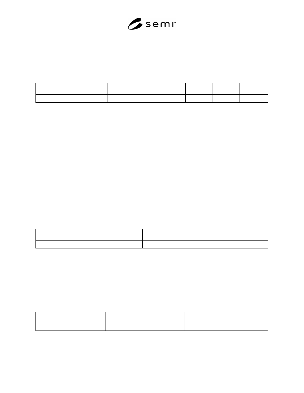
an attribute definition table with the following column headings:
Attribute Name Definition Access Requirement Form
The formal text name of the attribute. Description of the information contained. RO or RW Y or N (see below)
7.2.1 The Access column uses RO (Read Only) or RW (Read and Write) to indicate the access that service-users
have to the attribute.
7.2.2 A ‘Y’ or ‘N’ in the requirement (Rqmt) column indicates if this attribute must be supported in order to meet
fundamental compliance for the service.
7.2.2.1 The Form column is used to indicate the format of the attribute.
7.2.3 Formal Name of an Object — The text capitalizes formal object name references. Similar to the way
capitalization is normally used when discussing entities. When describing something in the general (like cities)
lower case is used, but when a specific entity is of interest (New York City), then first letters are capitalized.
7.2.4 Components of Complex Attributes — The names of object attributes defined in tables are left-justified. The
individual elements of complex attributes are right-justified in order of appearance below the complex attribute.
7.3 Service Message Representation — Services are functions or methods that may be provided by either the
equipment or the host. A service message may be either a request message, which always requires a response, or a
notification message, that does not require a response.
7.3.1 Service Definition
7.3.1.1 A service definition table defines the specific set of messages for a given service resource, as shown in the
following table:
Message Service Name Type Description
7.3.1.2 Type can be either “N” = Notification or “R” = Request & Response.
7.3.1.3 Notification type messages are initiated by the service provider (e.g., the equipment) and the provider does
not expect to get a response from the service user. Request messages are initiated by a service user (e.g., the host).
Request messages ask for data or an activity from the provider. Request messages expect a specific response
message (no presumption on the message content).
7.3.2 Service Parameter Dictionary
7.3.2.1 A service parameter dictionary table defines the description, format and its possible value for parameters
used by services, as shown in the following table:
Parameter Name Description Format: Possible Value
7.3.2.2 A row is provided in the table for each parameter of a service.