semi合集-English.pdf - 第502页
SEMI E72-0600 © SEMI 2003 4 Table 1 Equipment Footprint, Height, a nd Weight Dime nsions Symbol Used Value Specifi ed Dimension Description H 3.5 m (11 ft. 5 in.) maximum height of equipment in the main fab Hs 2 m (6 ft.…
SEMI E72-0600 © SEMI 1998, 2005 3
horizontal dimensions. Furthermore, none of these packages may weigh more than Mm each. This paragraph does
not apply to stockers and AMHS transport equipment.
5.4.2 Recommendations — Equipment suppliers and device manufacturers might also consider carrier stocker size,
move-in timing, and move-in path during stocker and facility design. Equipment that conforms to these limits may
still be too large to fit into standard truck trailers or aircraft cargo bays.
5.5 Maintenance Access
5.5.1 Requirements — To avoid interfering with carrier transport systems, equipment must not require regularly
scheduled maintenance from the front. This requirement does not apply to maintenance performed on user
interfaces, cart-docking interfaces, load ports, carrier buffers, and load locks.
5.5.2 Recommendations — It is recommended that as little regularly scheduled maintenance as possible be required
from the side.
5.6 Width vs. Depth
5.6.1 Recommendations — In general, to minimize the number of bays required in a fab, it is recommended that
equipment be designed to minimize width rather than depth.
5.7 Linked Equipment
5.7.1 Recommendations — To make linked equipment (such as cluster tools or steppers with litho tracks) jointly
space efficient, it is recommended that they be designed to minimize the cost footprint of the entire system as a
whole.
6 Related Documents
6.1 SEMI Standards
SEMI E6 — Facilities Interface Specifications Guideline and Format
SEMI E26.1 — Radial Cluster Tool Footprint 300 mm Standard
SEMI E35 — Cost of Ownership for Semiconductor Manufacturing Equipment Metrics
SEMI E76 — Guide for 300 mm Process Equipment Points of Connection to Facility Services
SEMI S2 — Safety Guidelines for Semiconductor Manufacturing Equipment
NOTICE: Unless otherwise indicated, all documents cited shall be the latest published versions.
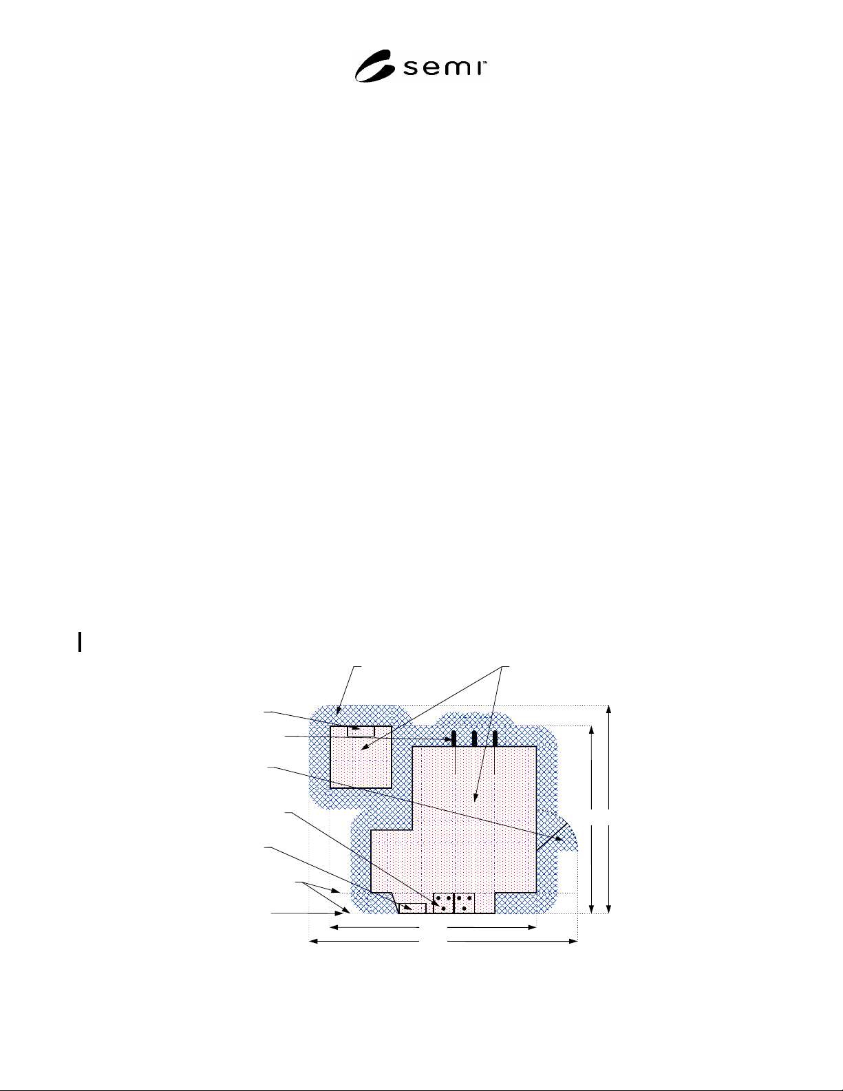
rear user
interface
utilities supply
access door
swing-out
E15.1-compliant
load ports and
carrier buffers
front user
interface
possible wall
locations, if any
(see SEMI 15.1)
load face plane
of the tool
Wt
Ws
Dt Ds
easement space
(required space
around the tool)
shadow footprint
(includes all
parts of the tool)
Figure 1
Equipment Footprint Dimensions
SEMI E72-0600 © SEMI 2003 4
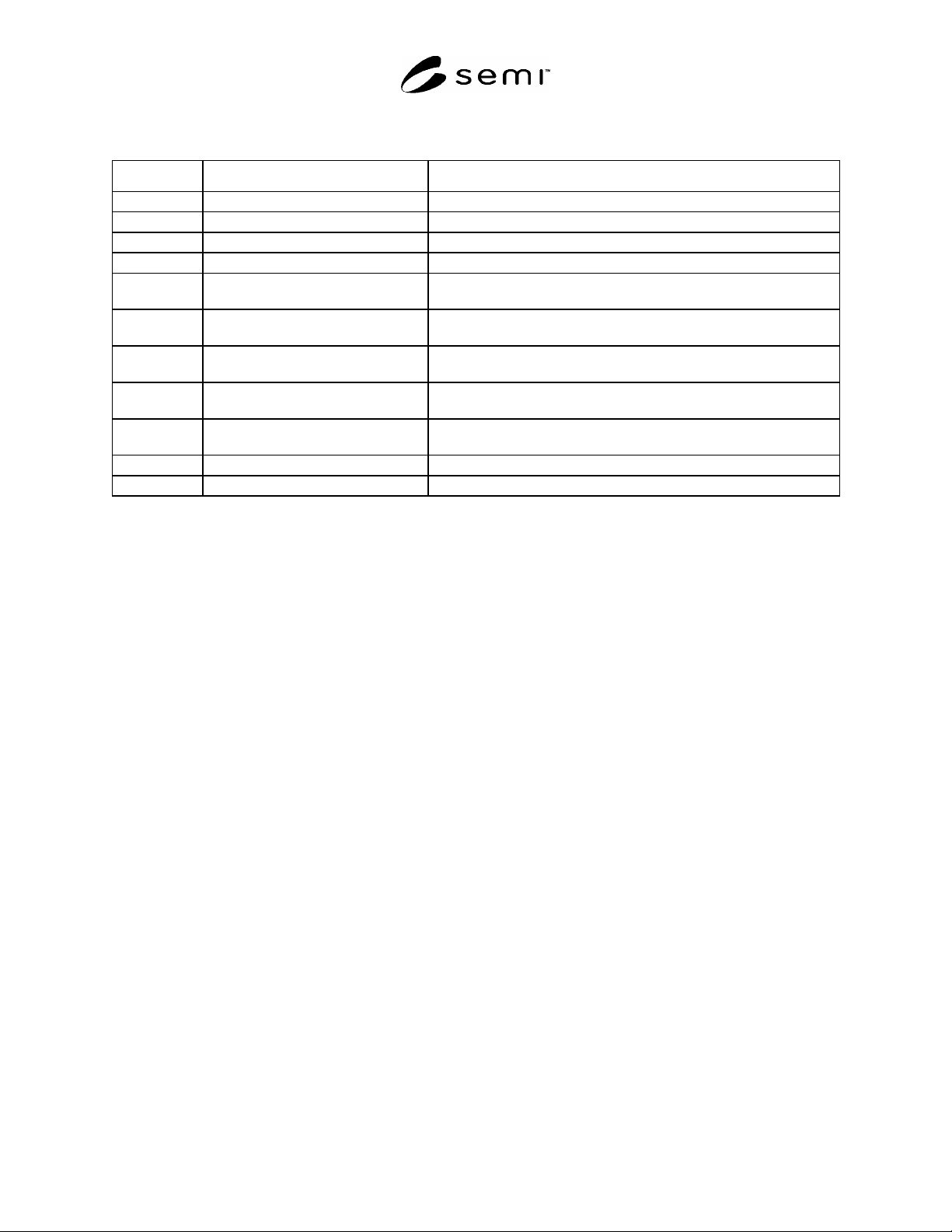
Table 1 Equipment Footprint, Height, and Weight Dimensions
Symbol Used Value Specified Dimension Description
H 3.5 m (11 ft. 5 in.) maximum height of equipment in the main fab
Hs 2 m (6 ft. 6 in.) maximum height of equipment in the sub-fab
M 1500 kg/m
2
(2.1 lbm./in.
2
) maximum mass of equipment divided by its shadow footprint
Mm 6000 kg (13227 lbm.) maximum mass of equipment move-in packages
Mt 1000 kg (2204 lbm.) maximum mass of equipment on any
0.6 m by 0.6 m (2 ft. by 2 ft.) floor tile
X 2.2 m (7 ft. 2 in.) maximum Length (perpendicular to Y) of equipment move-in packages destined
for the main fab
Xs 2 m (6 ft. 6 in.) maximum Length (perpendicular to Ys) of equipment move-in packages destined
for the sub-fab
Y 2.8 m (9 ft. 2 in.) maximum Length (perpendicular to X) of equipment move-in packages destined
for the main fab
Ys 1.7 m (5 ft. 6 in.) maximum Length (perpendicular to Xs) of equipment move-in packages destined
for the sub-fab
Z 2.8 m (9 ft. 2 in.) maximum Height of equipment move-in packages destined for the main fab
Zs 2 m (6 ft. 6 in.) maximum Height of equipment move-in packages destined for the sub-fab
SEMI E72-0600 © SEMI 1998, 2005 5
RELATED INFORMATION 1
APPLICATION NOTES
NOTICE: This related information is not an official part of SEMI E72 but was approved for publication by full letter
ballot procedures.
R1-1 The maximum height of equipment in the main fab was set so that the equipment could be installed in
existing fabs with ceilings just above the equipment height of 3.5 m (11 ft. 5 in) or in fabs with ceiling heights of
3.66 m (12 ft. 0 in.) where more clearance is provided for such things as parts of some overhead carrier transport
systems, fire sprinkler systems at the ceiling, and/or extra room for installation of equipment.
R1-2 The maximum height of equipment in the sub-fab was set so that no part of the equipment (other than
connections to the main fab area) sticks up into the piping and duct-work immediately under the waffle slab. In
those cases where a part of the equipment must be taller than 2 m (6 ft. 6 in.), it is recommended that it not be taller
than 2.5 m (8 ft. 2 in.) to stay under the waffle slab.
R1-3 If equipment must have easement space on the side, it is recommended that they be designed in mirror-image
configurations with easement space needed on only one side or the other, so that half of the total easement space on
the sides can be deleted. However, it is recommended that the resulting increase in equipment cost, complexity, and
spare parts inventory be taken into account.
R1-4 Equipment that conforms to the limits given in this standard may be too large or heavy to fit into buildings
that were originally designed for equipment that processes smaller wafers.
NOTICE: SEMI makes no warranties or representations as to the suitability of the standards set forth herein for any
particular application. The determination of the suitability of the standard is solely the responsibility of the user.
Users are cautioned to refer to manufacturer's instructions, product labels, product data sheets, and other relevant
literature, respecting any materials or equipment mentioned herein. These standards are subject to change without
notice.
By publication of this standard, Semiconductor Equipment and Materials International (SEMI) takes no position
respecting the validity of any patent rights or copyrights asserted in connection with any items mentioned in this
standard. Users of this standard are expressly advised that determination of any such patent rights or copyrights, and
the risk of infringement of such rights are entirely their own responsibility.
Copyright by SEMI® (Semiconductor Equipment and Materials
International), 3081 Zanker Road, San Jose, CA 95134. Reproduction of
the contents in whole or in part is forbidden without express written
consent of SEMI.