semi合集-English.pdf - 第6451页
SEMI G76-0299 © SEMI 1999 7 Figure 3 Electrodes for Measureme nt of Volume Resistivity 8.6.2 S urface Resistivity (1) Equ ipment Use the same equipm ent as in Section 8.6.1. (2) Materia l Use the same material as in …
SEMI G76-0299 © SEMI 1999 6
(3) Measurement After measuring the sample
cover film width, fix the sample in the pull
tester. In order to keep the sample at 90°, affix
a reinforcement panel with double-sided
adhesive tape. Pull and peel off more than 50
mm of cover film at a speed of 50 mm/min
-1
and an angle of 90 ± 5°. Measure the load
during this interval.
(4) Calculation Use the same method as Section
8.5.1, (4).
8.6 Electrical Efficiency Test
8.6.1 Volume Resistivity
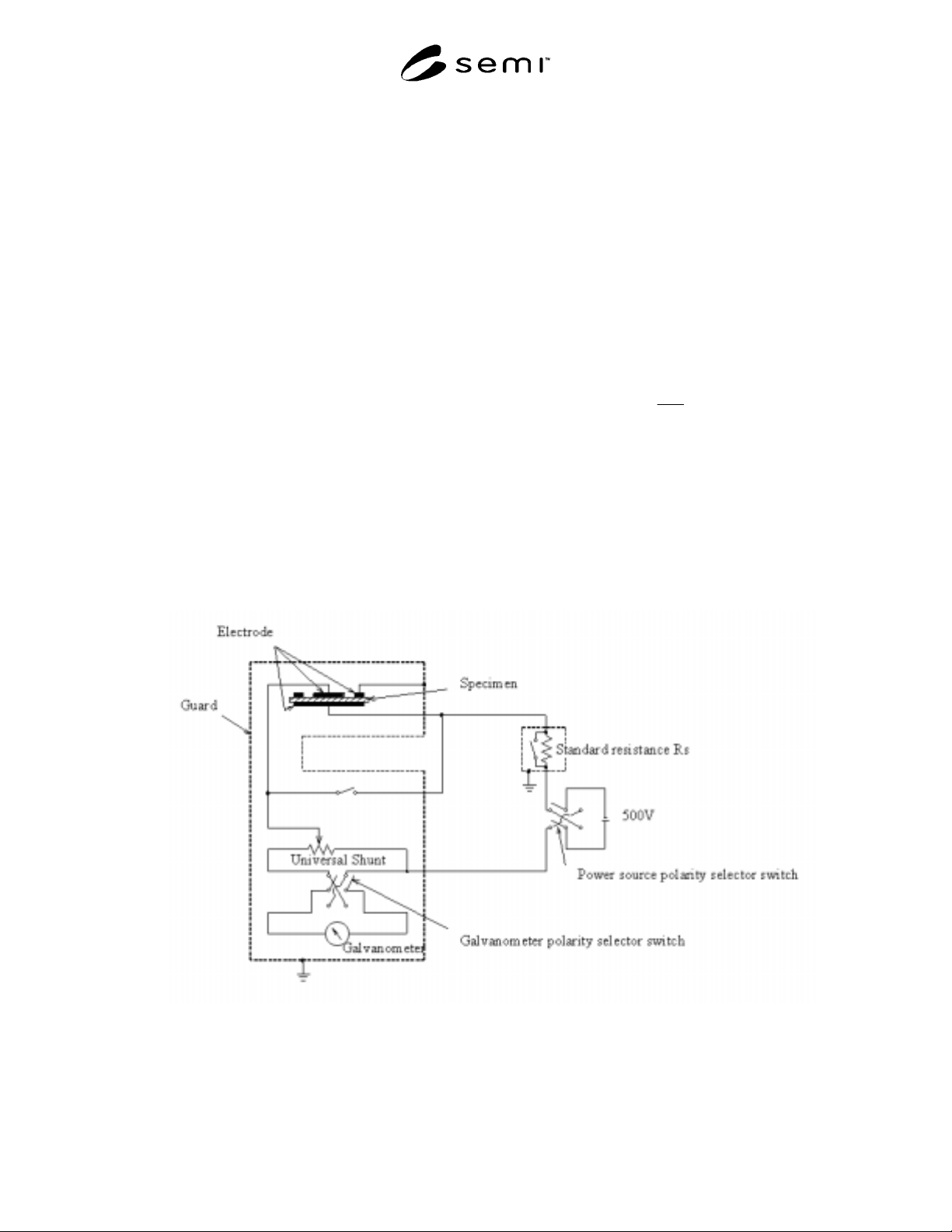
(1) Equipment Use high insulation-resistance
meter which conforms to JIS C-1303, or
similar resistance measuring device (see
Figure 2).
(2) Material - Prepare a section of TCP
polyimide adhesive tape with adhesive
material width of more than 50 mm, laminate
with copper foil and cure according to the
method described in Section 8.2. In addition,
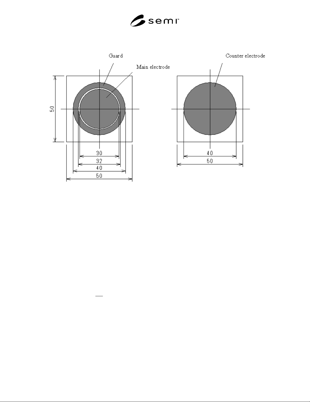
etch the main electrode and guard electrode
into the shapes found in Figure 3. For the
counter electrode, melt on a conductive
material to the opposing polyimide film
surface, or form it out of conductive paste. Dry
these at 80 ± 5°C for 30 minutes. Cut these
into 50 mm squares for the material.
(3) Measurement Use the following steps to
measure under normal conditions: Measure the
thickness of the samples in units of 0.1 µm,
and measure the inner diameter of the gap in
the circular upper electrode in units of 0.05
mm. Apply direct voltage of 500V ± 5V, and
measure the resistance value after 1 minute.
(4) Calculation Use the equation below.
)/(
4
1
cm
t
D
Rvv Ω×=
π
ρ
Where ρv is volume resistivity, Rv is resistance
value, t is sample thickness, π is pi, and D
1
is main
electrode outer diameter.
Figure 2
Resistance Measurement Device for Volume Resistivity
SEMI G76-0299 © SEMI 1999 7
Figure 3
Electrodes for Measurement of Volume Resistivity
8.6.2 Surface Resistivity
(1) Equipment Use the same equipment as in
Section 8.6.1.
(2) Material Use the same material as in Section
8.6.1.
(3) Measurement To measure Surface
Resistance in normal conditions, use the same
method as described in Section 8.6.1.
(4) Calculation Use the equation below.
)(
0
Ω×=
D
P
Rss
ρ
Where ρs is Surface Resistance, Rs is resistance
value, P is the actual circumference length of the
guarded electrode, and D
0
is the distance between
the main electrode and the guard electrode.
8.6.3 Insulation Resistance
(1) Equipment
(a) Resistance Meter Use the same
equipment as in Section 8.6.2.
(b) Direct Current Use a stabilized direct
power supply that can apply a stable 100
± 5V to the sample.
(c) Environmental Test Chamber Use an
oven with terminal connectors on the
outside which can maintain humidity at
30–85 ± 5°C and 60–90 ± 5% R.H.
(2) Material Using the TCP polyimide adhesive
tape as received from the vendor, laminate and
cure it according to the method described in
Section 8.2.
(3) Measurement
(a) Normal Condition Apply direct voltage
of 100 ± 5V to the sample and maintain
for 1 minute. Keeping the voltage applied,
measure the insulation resistance.
(b) High Temperature, High Humidity
After keeping the sample under 85 ± 5°C
and 85 ± 5% R.H. for 24 ± 4 hours,

SEMI G76-0299 © SEMI 1999 8
perform the same measurement as in
Section 8.6.3, (3)(a).
(c) High Temperature, High Humidity, Under
Bias After keeping the sample under
85 ± 5°C and 85 ± 5% R.H. for 24 ± 4
hours, apply direct voltage of 100 ± 5V
and perform the same measurement as in
Section 8.6.3, (3)(a). After this, follow the
methods and conditions defined by the
receiving parties.
8.6.4 Inter-Layer Voltage Resistance
(1) Equipment Use the equipment which
conforms to JIS C-2110, Section 6.2 or
similar.
(2) Material Use the same material prepared by
the same method as in Section 8.6.1, (2).
(3) Measurement To measure in normal
conditions, perform the following steps: Using
DC voltage, or a sine wave AC with 50 or 60
Hz frequency, apply 500V to the sample.
Increase the applied voltage up to the defined
voltage over 5 seconds, maintain it for 1
minute and determine whether there has been
any mechanical damage, flash-over, spark-
over, insulation breakdown or other
abnormality.
8.6.5 Relative Permittivity and Dielectric Dissipation
Factor
(1) Equipment
(a) Power Source (see Figure 4 - S) Use a
source which can emit a frequency of 1
MHz, has a sine wave with less than 5%
distortion factor, can give a stable flow of
the define voltage to the sample, and have
electro-static and magnetic shielding to
prevent direct coupling between the power
source and bridge.
(b) Shielded Transformer (see Figure 4 - T
1
)
Use a transformer with which the
power source internal impedance and the
bridge impedance can be adjusted, and
one where the winding on the bridge
inside the transformer is shielded with a
grounded conductor.
(c) Ratio Arm (see Figure 4 - T
2
) Use a
ratio arm with a winding ratio of 1:1
(tolerance of less than 0.2%). Make a non-
inductive connection of the primary
winding and secondary winding of a
transformer with as little leakage
inductance and winding resistance.
Ground the connection point as shown in
Figure 4 - e, and connect the other 2
terminals to l and r to make it unbalanced.
(d) Variable Capacitor (see Figure 4 - Cs
1
,
Cs
2
) Use two air capacitors with guards
that have a capacity of approximately 200
pF, one being the standard capacitor Cs
1
and the other being the measuring
capacitor Cs
2
, and insert parallel with the
sample Cx.
(e) Conductance Shifter (see Figure 4 - g)
Insert a resistor with a constant
conductance in between m and d in Figure
4, where the resistance between l and m
can be changed between 100–0 Ω, and the
resistance between m and r can be
changed between 100–200 Ω.
(f) Balance Detector (see Figure 4 - g) Use
a balance detector which responds only to
the power source voltage base plate used
in the bridge.
(2) Material Prepare the samples according to
the method described in Section 8.6.1, (3). Use
Figure 3 for the shape of the electrode.
(3) Measurement Use the following to measure
under normal conditions: Measure the
thickness of the samples in units of 1 µm, and
measure the inner diameter of the gap in the
circular upper electrode in units of 0.05 mm.
Also, confirm that the circular gap between the
main electrode and the guard electrode is 1 ±
0.1 mm. Connect the sample at position Cx,
and by adjusting the measuring capacitor Cs
2
and the conductance shifter, with the bridge
balanced, measure the standard capacitor Cs
1
value and the measuring capacitor Cs
2
value,
the resistance value between conductance
shifter m and d, and the resistance value
between m and r. The measuring frequency is
1 MHz.
(4) Calculation Use the equation below.
(a) Relative Permittivity
)(
0
Ω=
C
Cx
r
ε
Where Cx is the difference in the
capacitance values of standard capacitor Cs
1
and measuring capacitor Cs
2
(when the