semi合集-English.pdf - 第531页
SEMI E76-0299 SEMI 1998, 1999 11 Figure R1-3 Pre-facilitation Pedestal w ith Multiple Top M ounted Interface Panels R1-1.9 The Figure R1-3 also shows the facility line running thr ough the waffle slab dir ectly u…
SEMI E76-0299
SEMI 1998, 1999
10
e) large footprint and/or multiple module for
equipment,
f) large number of connections required for the
equipment (more than 10), and
g) peripheral components for the equipment
(pumps, RF generators, chiggers, etc.) are
typically located beneath the equipment in a
subfab area.
R1-1.6 The pre-facilitation pedestal is not
recommended for use when these conditions apply.
a) small table mounted equipment,
b) no more than one connection on the bottom of
the equipment,
c) other connections located on back, top, or side,
d) no maintenance, repair, or spill clean up access
requirements beneath equipment,
e) few connections required (less than 10), and
f) few if any peripheral components required or
located below equipment in subfab area.
R1-1.7 These conditions are only recommendations and
dialog between the supplier and device manufacturer is
recommended to determine if a pre-facilitation pedestal
is necessary or beneficial for a specific application.
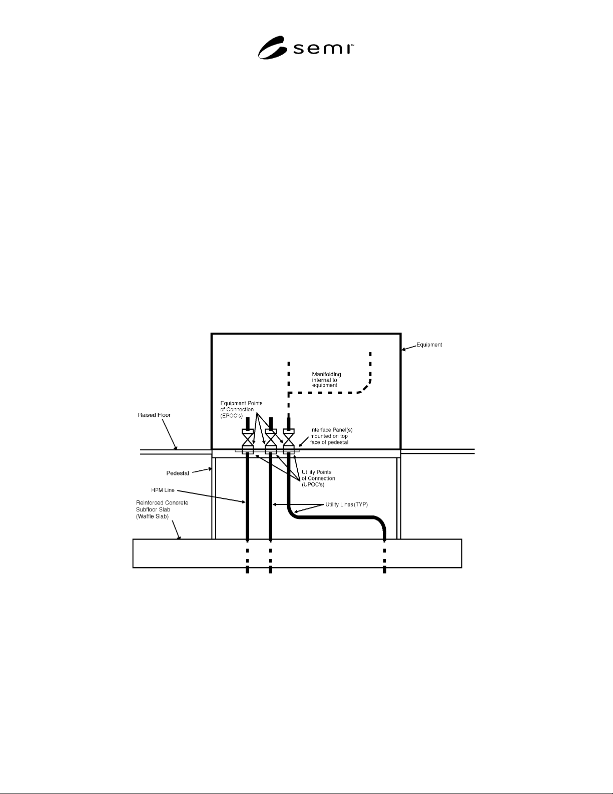
R1-1.8 The Figure R1-2 shows the facility utility lines
running up through the waffle slab directly underneath
the equipment. The UPOC - EPOC connections occurs
at the EPOC interface panel which is located on the top
plane of the pre-facilitation pedestal. This concept is
preferred by device manufacturers as the number of
connections are minimized, no additional space is
required on the sides or in back of the equipment for
routing, and the HPM lines can be pre-facilitation to the
UPOC without additional connections or special double
containment requirements.
Figure R1-2
Pre-facilitation Pedestal with Top Mounted Interface Panel
SEMI E76-0299
SEMI 1998, 1999
11
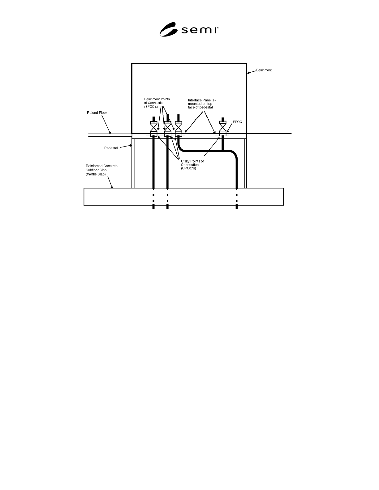
Figure R1-3
Pre-facilitation Pedestal with Multiple Top Mounted Interface Panels
R1-1.9 The Figure R1-3 also shows the facility line
running through the waffle slab directly underneath the
equipment. In addition, this example depicts situations
where there is a physical requirement to manifold
connections underneath the equipment. The same
advantages as Example #1 apply with the exception of
minimizing the number of connections to the
equipment.
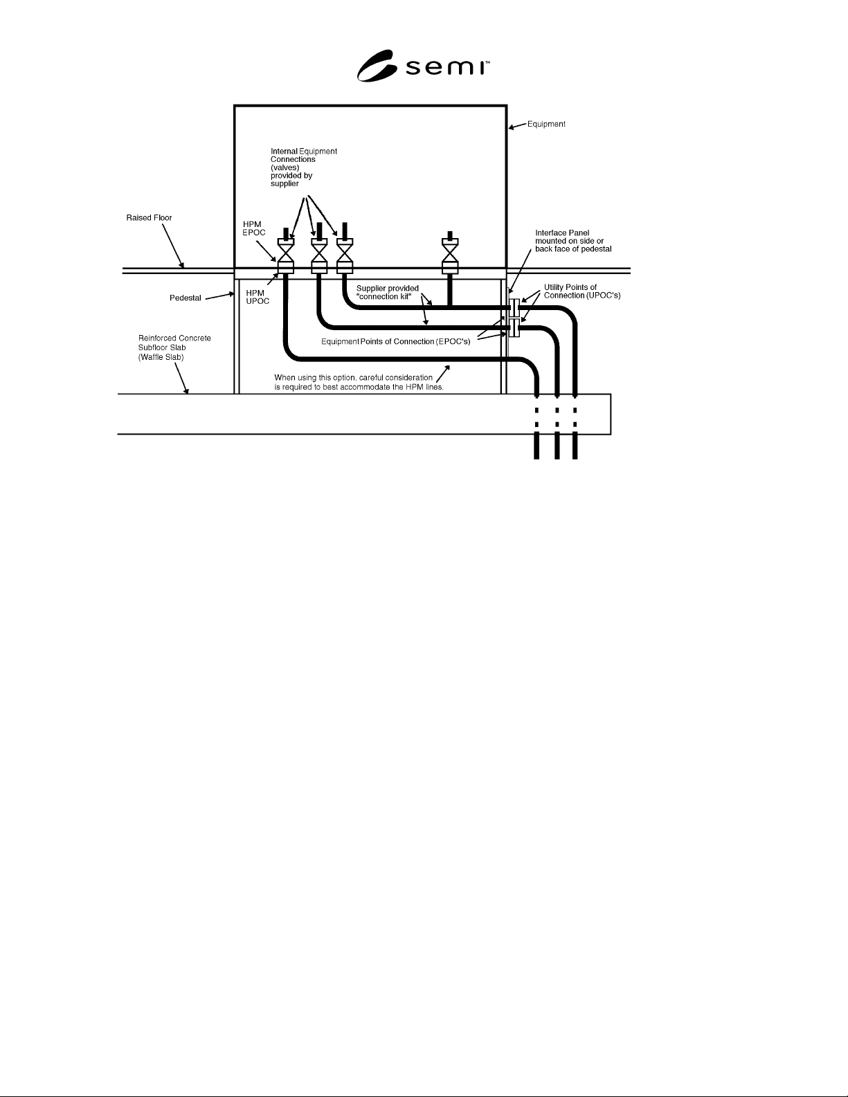
R1-1.10 The Figure R1-4 shows the facility utility lines
running up through the waffle slab to the side/back of
the pre-facilitation pedestal and connecting to the EPOC
interface panel mounted on the side/back of the pre-
facilitation pedestal. In this example a short section of
line is required to complete the connection from the
EPOC interface panel to the connection within the
equipment itself. This short section of line should be
prefabricated such that final hookup to the equipment
can be accomplished quickly once the equipment is set.
It is important to note that this option requires careful
consideration on how to accommodate HPM lines. It is
generally undesirable to have additional connections in
HPM lines or to design the pre-facilitation pedestal
itself to provide secondary containment. In this
example, the equipment supplier is responsible for the
volume in the pre-facilitation pedestal to route and
manifold the plumbing as required
SEMI E76-0299
SEMI 1998, 1999
12
Figure R1-4
Pre-facilitation Pedestal with Side/Back Mounted Interface Panels
NOTICE: These standards do not purport to address
safety issues, if any, associated with their use. It is the
responsibility of the user of these standards to establish
appropriate safety and health practices and determine
the applicability of regulatory limitations prior to use.
SEMI makes no warranties or representations as to the
suitability of the standards set forth herein for any
particular application. The determination of the
suitability of the standard is solely the responsibility of
the user. Users are cautioned to refer to manufacturer’s
instructions, product labels, product data sheets, and
other relevant literature respecting any materials
mentioned herein. These standards are subject to change
without notice.
The user’s attention is called to the possibility that
compliance with this standard may require use of
copyrighted material or of an invention covered by
patent rights. By publication of this standard, SEMI
takes no position respecting the validity of any patent
rights or copyrights asserted in connection with any
item mentioned in this standard. Users of this standard
are expressly advised that determination of any such
patent rights or copyrights, and the risk of infringement
of such rights, are entirely their own responsibility.
Copyright by SEMI® (Semiconductor Equipment and Materials
International), 3081 Zanker Road, San Jose, CA 95134. Reproduction o
f
the contents in whole or in part is forbidden without express written
consent of SEMI.