semi合集-English.pdf - 第2506页
SEMI E88-1104 E © SEMI 1999, 2004 3 5.2.18 Stocker Controller — stocker Eq uipment Controller that communica tes with the host and represents the system as the equi pment. 5.2.19 stocker crane — stocker transfer agent sp…

SEMI E88-1104
E
© SEMI 1999, 2004 2
SEMI E37 — High-Speed SECS Message Services
(HSMS) Generic Services
SEMI E37.1 — High-Speed SECS Message Services
Single Selected-Session Mode (HSMS-SS)
SEMI E84 — Specification for Enhanced Carrier
Handoff Parallel I/O Interface
4.2 Other References
Harel, D., “Statecharts: A Visual Formalism for
Complex Systems,” Science of Computer Programming
8 (1987) 231-274.
1
NOTICE: Unless otherwise indicated, all documents
cited shall be the latest published versions.
5 Terminology
5.1 Abbreviations and Acronyms
5.1.1 AMHS — Automated Material Handling System
5.1.2 BP — Buffer Port
5.1.3 FOUP — Front Opening Unified Pod
5.1.4 GEM — Generic Equipment Model
5.1.5 IBSEM — InterBay/IntraBay Specific Equipment
Model
5.1.6 ITS — Interbay or Intrabay Transport System
5.1.7 LP — Loading Port
5.1.8 OP — Output Port
5.1.9 PGV — Person Guided Vehicle
5.1.10 SC — Stocker Controller
5.1.11 TCP/IP — Transmission Control
Protocol/Internet Protocol
5.1.12 TSC — Transport System Controller
5.2 Definitions
5.2.1 Automated Material Handling System — an
automated system to store and transport materials
within the factory.
5.2.2 automation — the capability of managing
material and data within the factory.
5.2.3 bidirectional load port — a load port used for
loading and unloading carriers.
5.2.4 buffer — a set of one or more locations for
holding carriers at the production equipment.
5.2.5 buffer port — special buffer port location on a
stocker output shuttle. Contains carrier presence
1 Elsevier Science, P.O. Box 945, New York, NY 10159-0945,
http://www.elsevier.nl/homepage/browse.htt
sensors so that the host can be notified when a carrier is
situated at this position.
5.2.6 carrier — a container with one or more fixed
positions for holding substrates. Examples of carriers
include FOUPs and open cassettes.
5.2.7 carrier ID — a readable and unique identifier for
the carrier.
5.2.8 FOUP—a closed carrier for holding wafers.
5.2.9 host — the factory computer system, or an
intermediate system, that represents the factory and the
user to the equipment. Refers system that controls or
supervises the Stocker Controller (SC) throughout this
document.
5.2.10 independent port — a load port on the stocker
that is dedicated to input or output. It is considered that
the carriers can only be transferred in one direction.
5.2.11 interbay transport system — a transport system
used to move work-in-process between stockers in
different parts of the factory.
5.2.12 Intrabay Transport System — a transport
system dedicated to one or more bays in the factory and
responsible for transferring carriers to and from
production equipment. ITS consists of the physical
units of the system (e.g., vehicles, nodes, docking
stations), the low-level unit controllers, and a system-
level controller. ITS excludes factory floor storage
systems (stockers), but includes any short-term storage
integral to the system, such as storage locations within
an overhead track system that are accessible only to
units of the particular ITS.
5.2.13 load port — the interface location on the
equipment where carriers are transferred.
5.2.14 loading port — user or vehicle accessible port
location on a stocker output shuttle. Contains carrier
presence sensors so that the host can be notified when a
carrier is situated at this position.
5.2.15 output port —port location on a stocker output
shuttle, typically accessible by the stocker crane.
Contains carrier presence sensors so that the host can be
notified when a carrier is situated at this position.
5.2.16 process equipment — equipment used to make
semiconductor devices. This excludes metrology and
material handling equipment.
5.2.17 production equipment — equipment used to
produce semiconductor devices, including wafer
sorting, process, and metrology equipment and
excluding material handling equipment.
SEMI E88-1104
E
© SEMI 1999, 2004 3
5.2.18 Stocker Controller — stocker Equipment
Controller that communicates with the host and
represents the system as the equipment.
5.2.19 stocker crane — stocker transfer agent
specialized for the movement of carriers between
shelves and input and output port locations.
5.2.20 stocker equipment — an individual stocker
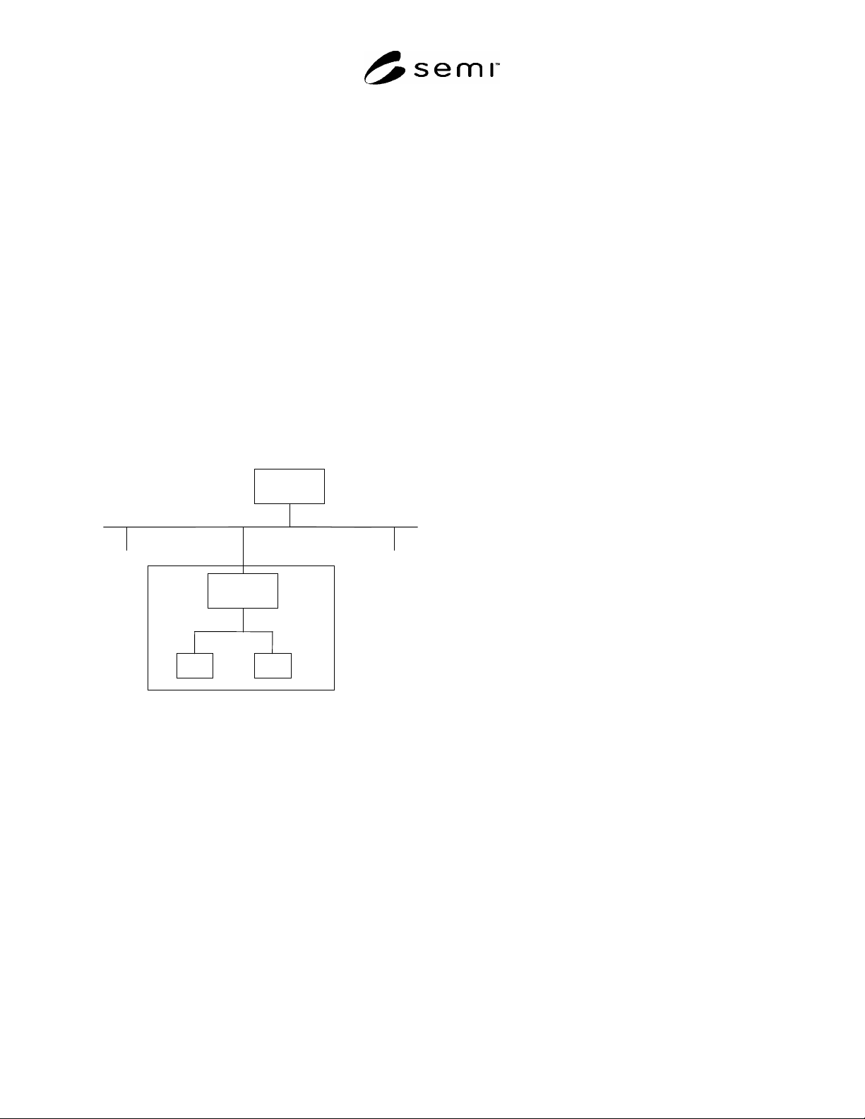
viewed as a single piece of equipment, with distributed
components and distributed control, as illustrated in
Figure 1. The stocker controller communicates with the
host using HSMS and GEM and represents the system
as an equipment. The factory may require more than
one type of stocker.
5.2.20.1 Communications with transport system
equipment may require a low-level handshake with a
transport unit directly involved in the transfer of
material (such as a vehicle or a docking station on an
overhead track).
5.2.20.2 Communications between the various stocker
units and controllers are proprietary to the supplier.
Stocker
Controller
internal proprietary
communications
Factory Host
Stocker
Equipment
host/equipment
communications
factory network
Stocker
Unit
Stocker
Unit
Figure 1
Example of Stocker Equipment
5.2.21 stocker shelf — locations within the stocker
equipment to store carriers. These locations exclude
load ports.
5.2.22 stocker unit — a physical component of the
stocker system, such as a stocker crane, ID reader,
wafer sensor, shuttle port, etc.
5.2.23 swapping port — a load port on the stocker
capable of handling single load and unload of carriers
or simultaneous replace of carriers.
5.2.24 transfer agent — a component of equipment
specialized to the movement of transfer objects from
place to place within a factory. May be of different
types with widely-differing characteristics. Examples
are fixed-arm robots, robot arms on fixed tracks,
overhead gantries or even systems containing a
heterogeneous collection of other transfer agents.
Humans may also act as transfer agents.
5.2.25 transfer completed port — the destination port
specified in a transfer command.
5.2.26 transfer port — point on the transport system at
which a change of equipment ownership of the carrier
occurs.
5.2.27 transfer unit — the element of movement
(assemblage of carriers) of the ITS that consists of a
maximum number of carriers allowed in a specific
transfer command:
AA is the maximum number of carriers allowed for
acquire at the transfer source.
BB is the maximum number of carriers allowed for
deposit at the transfer destination.
CC is the maximum number of carriers allowed for
transfer in one transport vehicle.
5.2.27.1 The maximum size of the transfer unit is the
minimum of AA, BB, and CC.
5.2.27.2 For purposes of the Stocker SEM, the transfer
unit is limited to one carrier.
5.2.28 transport system — the component of AMHS
that moves material from one part of the factory to
another.
5.2.29 transport unit — a physical component of a
transport system, such as a vehicle, node, or docking
unit.
5.2.30 zone — a logical assignment referencing a set of
one or more locations. A stocker can have several
logical zone assignments. For example, a specific
stocker may have 2 zones defined as LEFT_ZONE and
RIGHT_ZONE. The assignment of zones is specific to
the Stocker SEM equipment supplier and it may be
desirable for the supplier to remain flexible in the
assignment of zones so that it could be configured to
meet the specific requirements of different users. A
specific zone may only contain shelf locations or ports,
but not both. A location may be in at most one zone.
6 Overview and Assumptions
NOTE 1: This section has been included as background
information to help clarify requirements.
6.1 Destination Control (to Shelf or to Output Port)
6.1.1 The destination is controlled by Host when the
carrier is input to the stocker (i.e., the carrier enters the
stocker domain). The destination of the transfer
command is required. It would be invalid for the Host
to issue a transfer command to the SC without
including a valid destination.

SEMI E88-1104
E
© SEMI 1999, 2004 4
6.1.2 Output to the Interbay Output Port
6.1.2.1 The destination for a transfer command to
move a carrier to an interbay output port must be a
loading port. It is the responsibility of the Host to
ensure that sufficient capacity exists in the destination
stocker when delivering from a source stocker to a
destination stocker (i.e., an interbay move). For
example, it would be the responsibility of the Host to
check the remaining capacity of the destination stocker
prior to issuing the transfer command to send the carrier
to the interbay output port of the source stocker.
6.1.3 Output to the Intrabay Output Port
6.1.3.1 The destination for a transfer command to
move a carrier to an intrabay output port must be a
loading port.
6.1.4 Store to the Stocker Shelf
6.1.4.1 The specific stocker shelf location is to be
controlled by the Stocker Controller (SC). The Host
does not specify a shelf ID in a transfer command. The
Host sends the name of a zone as the destination in the
transfer command
6.1.4.2 The carrier is stored to a stocker shelf
temporarily when the Host requested output port
destination is occupied. This is the responsibility of the
Stocker Controller. The carrier count of the stocker is
incremented due to this temporary storage (i.e., the
current capacity decreases).
6.1.4.3 For multi-crane stockers, the carrier is
temporarily stored to a stocker shelf when the source
and destination is not accessible by the same stocker
crane. This is the responsibility of the Stocker
Controller. The carrier count of the zone containing the
location where the carrier is temporarily stored is
incremented due to this temporary storage (i.e. the
current capacity decreases).
6.2 Quantity Control in the Stocker (Capacity
Planning)
6.2.1 The number of carriers in the stocker is
controlled by the Host. A list of carrier database entries
in the specified stocker’s SC database will be available
to the Host upon request via a remote command.
6.3 Number of Stocker Cranes
6.3.1 No Limitation. May be zero for systems that do
not include a crane. Host does not control the stocker
crane directly.
6.4 Port Type
6.4.1 The independent input port and the independent
output port are required for the Stocker SEM. The
swapping type is considered as an independent port.
6.5 Plural Sets of Input/Output Ports
6.5.1 Plural sets of Input/Output ports connected to the
interbay or intrabay transport system must be
considered. (This would be considered a Multi-loop
type interface connection to the stocker.) Examples of
plural sets of interfaces are as follows:
Main Loop/Sub Loop,
Right-handed rotation/Left-handed rotation, and
Double Track (i.e., Stacked Track).
6.6 Carrier ID Reader
Manual Input Port: Carrier ID Reader is
mandatory.
Automated Input Port: Carrier ID Reader is a
customer option.
Carrier ID Reader at any output port: Carrier ID
Reader is a customer option.
6.6.1 The intrabay automated input port is sometimes
used as the manual Input Port. If one port is used for
both an automated and a manual, the Carrier ID Reader
is mandatory for this port. If there is a Carrier ID
Reader, the scenario for a stocker transfer without a
Carrier ID Reader is not applicable.
6.7 Tag
6.7.1 Same assumptions as Carrier ID Reader.
6.8 Carrier Exchanger/Gas Purger
6.8.1 Out of scope of Stocker SEM.
6.9 Robot Arm in the Passive Type Stocker
6.9.1 No assumption is made regarding the passive
type stocker.
6.10 Empty or Not Empty Carriers
6.10.1 No assumption is made regarding empty and not
empty carriers.
6.11 Monitor/Dummy
6.11.1 No assumption.
6.12 Operation Mode
6.12.1 No assumption.