semi合集-English.pdf - 第3936页
Table 1 Filter and Purifier Interface Recommendations Filter and Purifier End-to-End Lengths: 1/4-inch Integral/fixed male face seal 1/4-inch Swivel face seal (male o r female) 1/4-inch Tube weld 84 mm (3.31 in.) - - NOT…
5.1.7 purifier an in-line device used for the removal of homogeneous impurities from gases, typically consisting
of a packed-bed of active solids contained in a stainless steel housing. The active purification media may remove
impurities such as moisture, oxygen, CO, CO
2
, hydrocarbons, hydrogen, or nitrogen from specific gases using a
variety of chemical reaction, physisorption, or chemisorption mechanisms. Point-of-use purifiers often contain a
particle filter within the same housing.
5.1.8 valve a device that controls the flow or pressure of a gas. Valve functions can include shutoff, metering,
backflow prevention, and pressure relief.
6 Ordering Information
6.1 Device manufacturers may use this guide when procuring processing equipment to communicate to the
equipment supplier the interface specifications required for interchangeability of components. This document may
also be used by semiconductor processing equipment suppliers to specify standardized interfaces to component and
module suppliers.
6.2 Orders for components in accordance with this standard shall include:
6.2.1 This standard number and date of issue.
6.2.2 Reference to the table number.
6.2.3 Reference to the option number, if applicable.
7 Filters and Purifiers
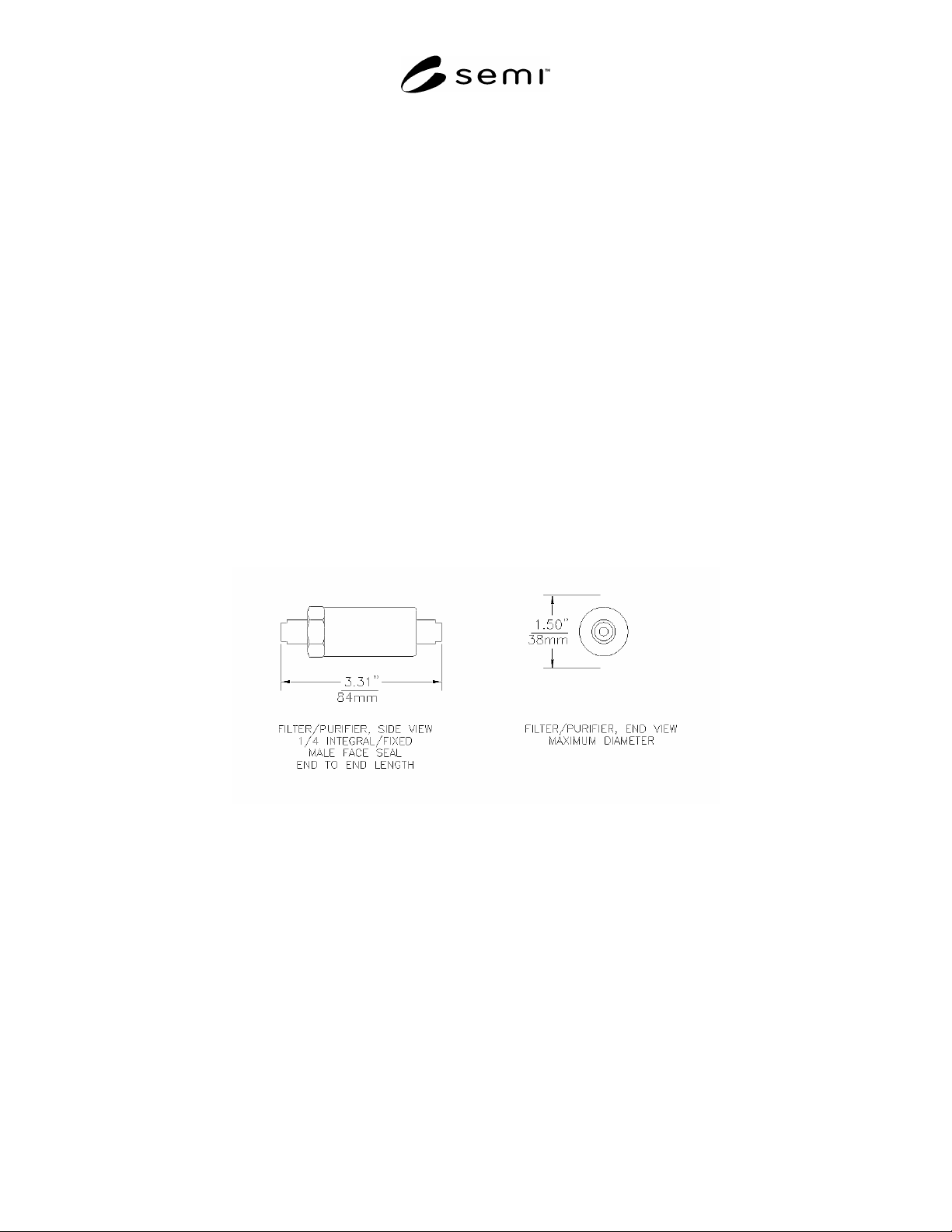
7.1 Filters less than 30 SLM and purifiers less than 1 SLM should conform to the interface design recommendations
appearing in Figure 1 and Table 1.
Figure 1
Filter and Purifier Interface Design
SEMI F36-0299 © SEMI 1999, 2004 2
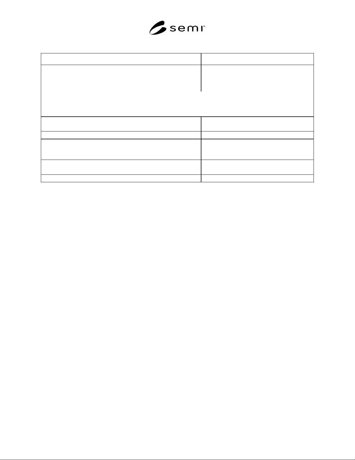
Table 1 Filter and Purifier Interface Recommendations
Filter and Purifier
End-to-End Lengths:
1/4-inch Integral/fixed male face seal
1/4-inch Swivel face seal (male or female)
1/4-inch Tube weld
84 mm (3.31 in.)
-
-
NOTE 1: The tolerance on length for machined components is ± 0.15 mm (0.006 in.) from the component centerline to each
end.
NOTE 2: The tolerance on length for welded components is ± 0.5 mm (0.020 in.) from the component centerline to each end.
Overall Component Envelope:
Maximum Diameter
38 mm (1.5 in.)
Base to Centerline of Flow Path:
-
Mounting provisions:
Threaded holes
Pattern
None required
-
Fittings:
Process
1/4-inch
Control:
None required
SEMI F36-0299 © SEMI 1999, 2004 3

8 Shut-off Valves
8.1 Shut-off valves should conform to the interface design recommendations appearing in Figure 2 and Table 2.
Figure 2
Shut-off Valve Interface Design
SEMI F36-0299 © SEMI 1999, 2004 4