semi合集-English.pdf - 第6348页
5 SEMI G69-0996 © SEMI 1996, 2004 9.4 Set the transfer molding pr essure, transfer time and cure time to the following reco mmended molding conditions. If the cond ition is not suitable for the material, t h e condition …
SEMI G69-0996 © SEMI 1996, 2004 4
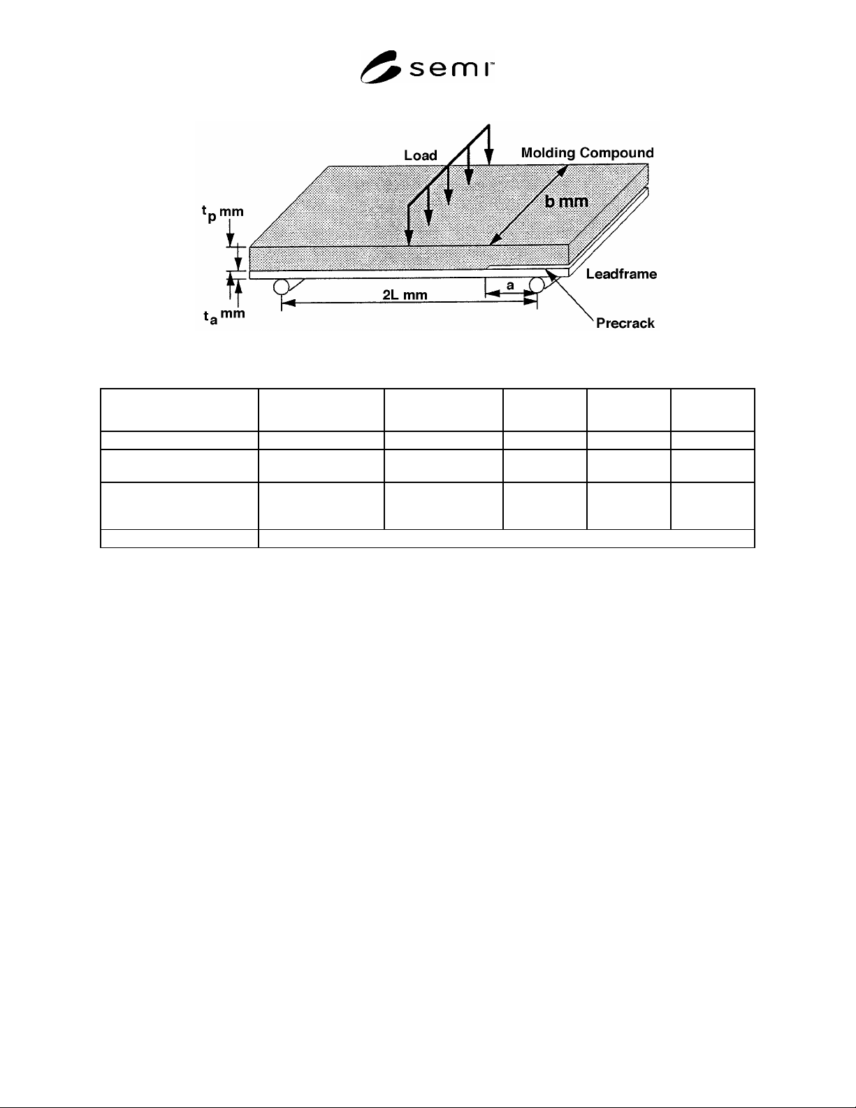
Figure 3
Sample for Three-Point Bending Method
Molding Compound
Thickness t
p
(mm)
Leadframe Thickness
t
a
(mm)
Span 2L (mm)
Pre-Crack
Length a (mm)
Sample Width
b (mm)
Standard 1.5 0.25 45 10–15 6
Type A
(for low adhesive strength)
0.8 0.2 35 8–10 4
Type B
(for high temperature
measurement)
4 0.5 50 10–15 6
Other Sample Types The following equations should be satisfied 2L 8 (t
p
+ t
a
) and L - a 2 (t
p
+ t
a
)
7 Sampling Plan
7.1 The sampling plan shall be in agreement between customer and vendor. It is recommended that the following
minimum sample sizes are used:
Shear Method — Four (4) samples
Pull Method — Four (4) samples
Three-Point Bending Method — Three (3) samples in each direction
NOTE 1: Three-point bending method needs at least 2 samples to obtain adhesive strength.
8 Materials
8.1 Leadframe or appropriated sample from strip meeting dimensions for test.
8.2 Molding compound
9 Sample Preparation
9.1 Leadframe Sample Preparation
9.1.1 Process the leadframe samples through the various cleaning and heat cycles that would be normal for the
leadframe under consideration as required.
NOTE 2: When this method is applied to copper leadframes, copper oxide on the surface shall be considered when results are
interpreted.
9.2 Clean and condition the molds to provide well formed samples as required.
9.3 Set the molds to the specified temperature and record the temperature.

5 SEMI G69-0996 © SEMI 1996, 2004
9.4 Set the transfer molding pressure, transfer time and
cure time to the following recommended molding
conditions. If the condition is not suitable for the
material, the condition should be agreed between
customer and vendor.
Molding condition
Cure temperature 170–180°C
Cure time 120 sec.
Molding pressure 6.8–7.8 MPa (70–80 kgf/cm
2
)
9.5 Mold all the required samples.
9.6 Remove the samples from the molds.
NOTE 3: After removing the samples from the molds, natural
cooling of the samples is recommended.
9.7 Post mold cure the samples at the following
recommended conditions.
Post-cure condition
Temperature
175 ± 5°C
Time 4–8 hours
9.8 Store the samples and record the storage
conditions.
9.9 Three-Point Bending Samples
9.9.1 In addition to the treatment mentioned in Section
10.1.1, and to facilitate cracking during the three point
bending method, apply a thin layer of mold release to
on end of the leadframe sample in order to form a “pre-
crack” condition (i.e., the molding compound will not
adhere to this section of the sample, see Figure 3).
NOTE 4: It is recommended that toluen-based thermosetting
silicone be used as a mold release agent to prevent molding
process contamination.
10 Calibration
10.1 Tensile Tester Calibration
10.1.1 Calibrate the tensile tester in accordance with
the manufacturer’s instructions.
11 Test Procedure
11.1 Shear Method
11.1.1 Attach the sample to the tensile test such that
shear may be applied.
11.1.2 Place the shear tool against the molding
compound formation and initiate a load at a constant
speed between 2–10 mm/min while recording the load
and displacement.
11.1.3 Record the peak load before the sudden drop in
applied load as the sample shears off the leadframe or
the molding compound breaks.
NOTE 5: Disregard any results which have the appearance of
sample slipping or shear tool riding over the molding
compound.
11.2 Pull Method
11.2.1 Attach the sample to the tensile tester such that
the leadframe may be pulled out of the molding
compound with a vertical pull action.
11.2.2 Attach the pulling grips to the leadframe and
initiate a load at a constant speed between 2–10
mm/min. while recording the load and displacement.
11.2.3 Record the peak load before the sudden drop in
applied load as the sample is pulled from the molding
compound samples.
NOTE 6: Disregard any results which have the appearance of
slippage of the sample or pulling grips.
11.3 Three-Point Bending Method
11.3.1 Measurement of the pre-crack length
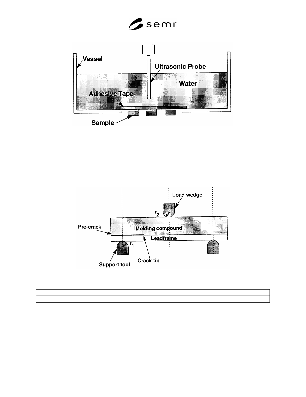
11.3.1.1 Measure the pre-crack length using an
ultrasonic inspection technique (see Figure 4).
NOTE 7: The sample, in this case, is placed in the vessel
with the leadframe side up, and then secured with an adhesive
tape so that the water cannot penetrate into the interface area
created by the mold release.
SEMI G69-0996 © SEMI 1996, 2004 6
Figure 4
Measurement of Pre-Crack Length
11.3.2 Test Procedure
11.3.2.1 Attach support fixture and load wedge to the tensile tester.
11.3.2.2 Place the sample on the support fixture with the molded side up (see Figure 5).
NOTE 8: The support fixture tool should be located at a constant distance from the tip of pre-crack for every measurement.
Figure 5
Sample Setup
Radius of support tool r
1
5–8 mm
Radius of load wedge r
2
2–5 mm
11.3.2.3 Place the load wedge in contact with the molded surface and initiate the loading at a constant speed
between 2–10 mm/min while recording the load and displacement.
11.3.2.4 Record the peak load before the sudden drop in applied load.
11.3.2.5 Repeat the test with another sample which has the leadframe side up.