semi合集-English.pdf - 第6365页
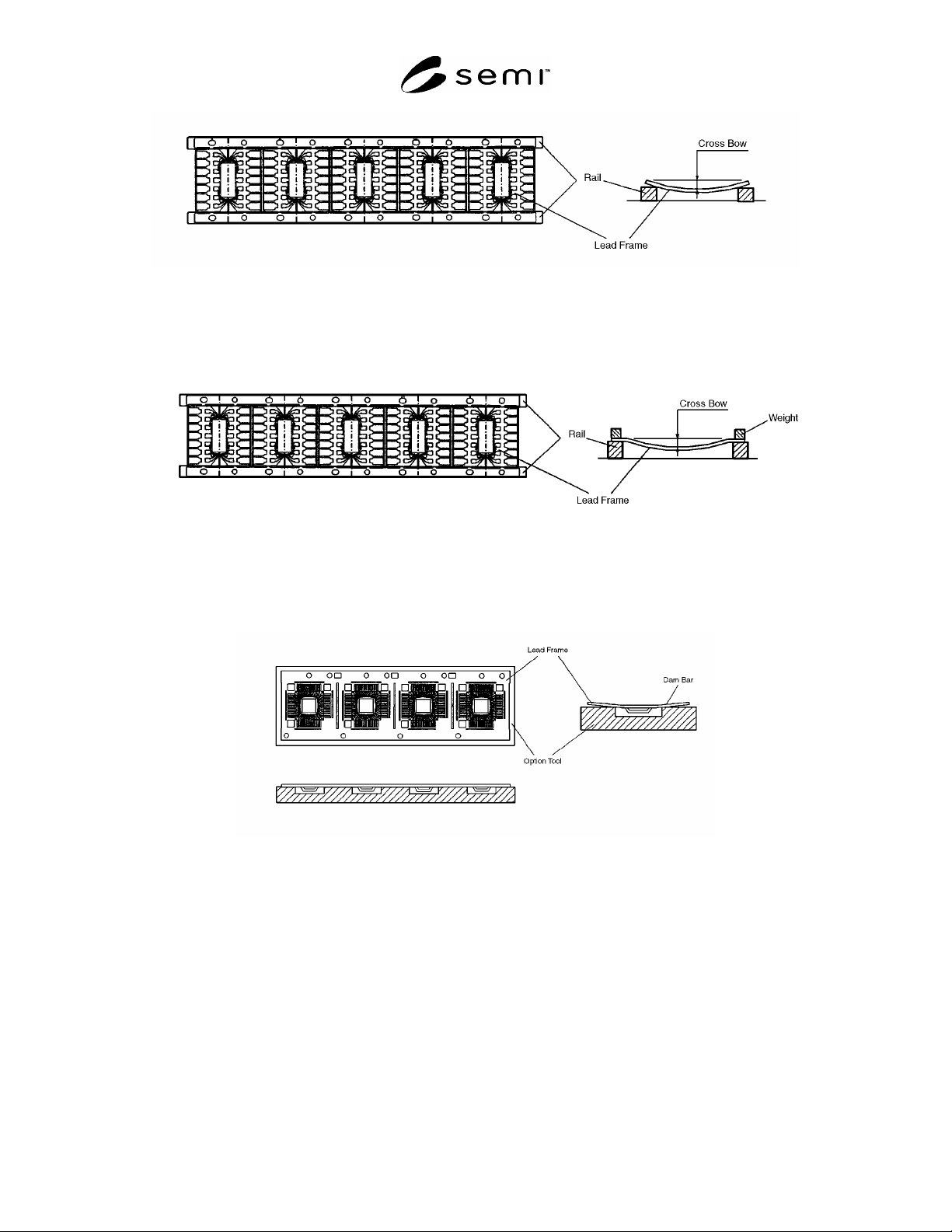
SEMI G70-0996 © SEMI 1996, 2004 6 Figure 16 Leadframe Fi xture — Type 1 Figure 17 Leadframe Fi xture — Type 2 Figure 18 Leadframe Fi xture — Type 3
5 SEMI G70-0996 © SEMI 1996, 2004
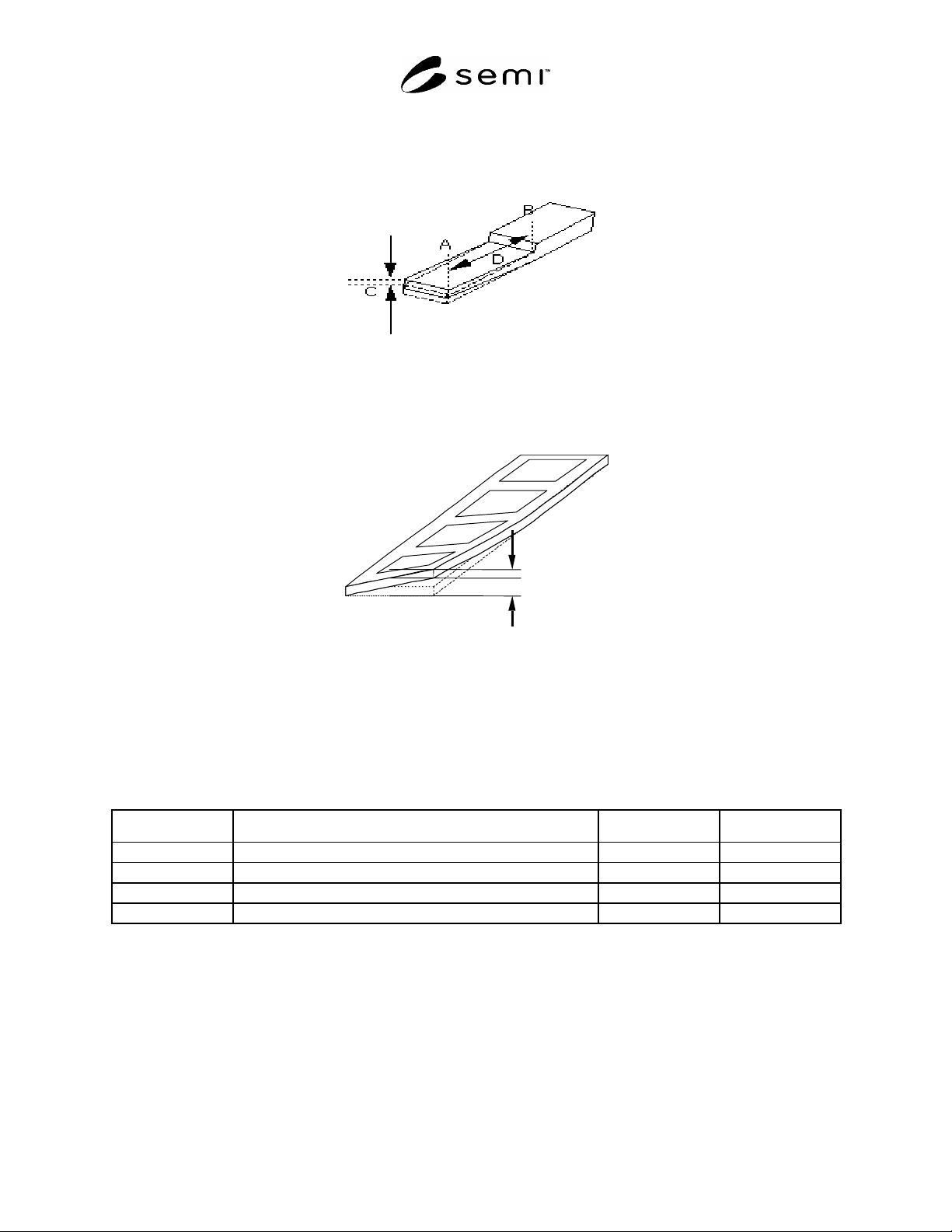
4.1.17 lead tilt — deviation of the plane of coined area from a condition parallel to the plane formed by the dam
bars (see Figure 14).
Figure 14
Lead Tilt
4.1.18 leadframe twist — angular rotation of one end of the leadframe or strip with reference to the other end (see
Figure 15).
B
A
C
Figure 15
Leadframe Twist
5 Equipment
5.1 Measurement Equipment — The equipment and required accuracy used for the measurements are shown in
Table 2.
Table 2 Measurement Equipment
Type Equipment Minimum Reading
Accuracy (2
A Height measurement equipment with non-contact method 0.1 µm 1 µm
B 1 µm 4 µm
C Clearance gage 10 µm -
D Scanning probe microscope 0.1 µm -
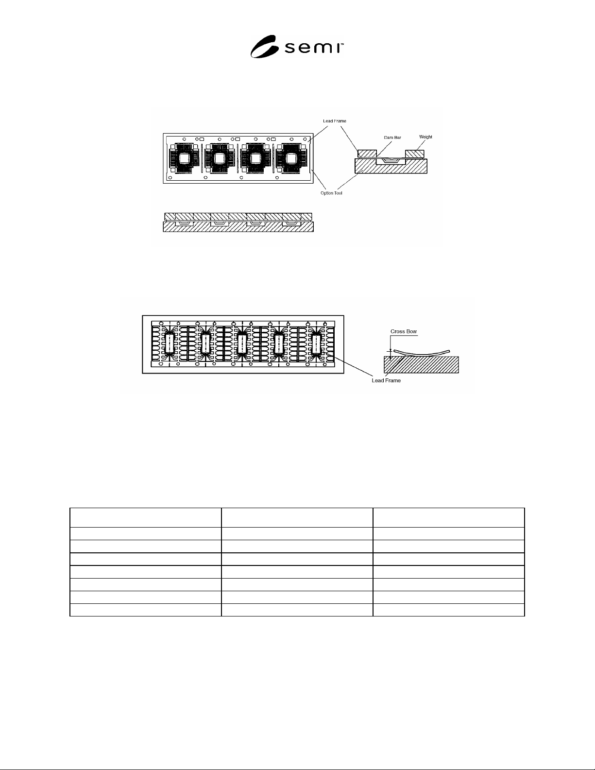
5.2 Leadframe Fixtures — Leadframe fixtures are shown in Figures 16–20. The materials, dimensions, and
accuracy shall be agreed between the vendor and customer.
SEMI G70-0996 © SEMI 1996, 2004 6
Figure 16
Leadframe Fixture — Type 1
Figure 17
Leadframe Fixture — Type 2
Figure 18
Leadframe Fixture — Type 3
7 SEMI G70-0996 © SEMI 1996, 2004
Figure 19
Leadframe Fixture — Type 4
Figure 20
Leadframe Fixture — Type 5
6 Measurement
6.1 Leadframe fixtures and measurement equipment for each measurement item are shown in Tables 3 and 4.
Table 3 Leadframe Fixtures and Measurement Equipment (Independent of Package Type)
Items Leadframe Fixture Equipment
Burr height 1. 2. 3. 4. 5. A. B. D.
Coil set 5 A. B. C.
Coined depth 1. 2. 3. 4. 5. A. B.
Die pad dimple depth 1. 2. 3. 4. 5. A. B.
Lead lock groove depth 1. 2. 3. 4. 5. A. B.
Half-etch depth 1. 2. 3. 4. 5. A. B.
Leadframe twist 1. 2. 3. 4. 5 A. B.