semi合集-English.pdf - 第6362页
3 SEMI G70-0996 © SEMI 1996, 2004 4.1.8 die pad locati on — deviation of the center point of die pad su rface from a plane established by the dam bars (see Figure 7). Figure 7 Die Pad Location 4.1.9 die pad tilt — deviat…
SEMI G70-0996 © SEMI 1996, 2004 2
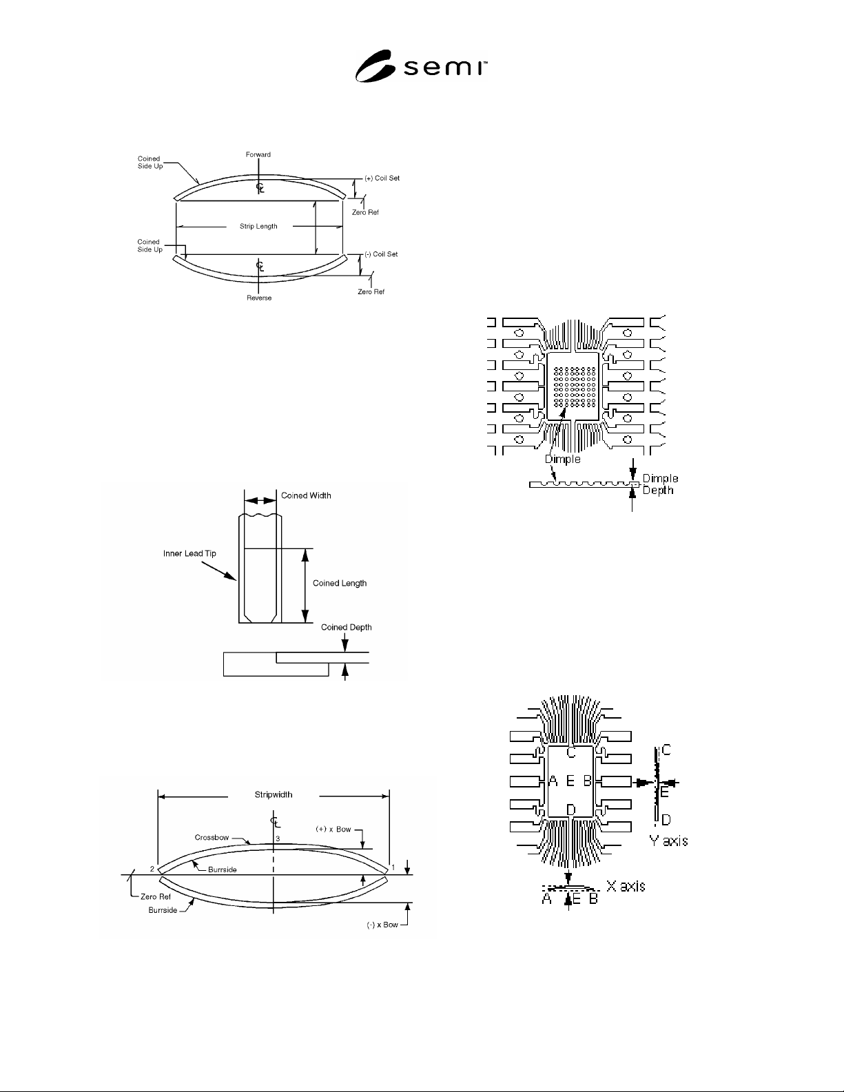
4.1.2 coil set — longitudinal bowing of the leadframe
strip length (see Figure 2).
Figure 2
Coil Set
4.1.3 coined depth — the difference in height between
the top surface of the coined area of an inner lead and
the top surface of the coined area at the tip of the lead.
Inner lead coining produces a flattened section of the
lead that is suitable for wire bonding (see Figure 3).
Figure 3
Coined Depth
4.1.4 crossbow — transverse bowing of the leadframe
(see Figure 4).
Figure 4
Crossbow
4.1.5 die pad dimple — a hollow formed in a die pad
using a half-etching technique or stamping to improve
the adhesive strength with the die or molding
compound and to reduce the stress between the die pad
and the die.
4.1.6 die pad dimple depth — the maximum depth of
the dimple (see Figure 5).
Figure 5
Die Pad Dimple Depth
4.1.7 die pad flatness — deviation of the center point
of die pad surface from a plane established by the four
corner points of die pad (see Figure 6).
Figure 6
Die Pad Flatness
3 SEMI G70-0996 © SEMI 1996, 2004
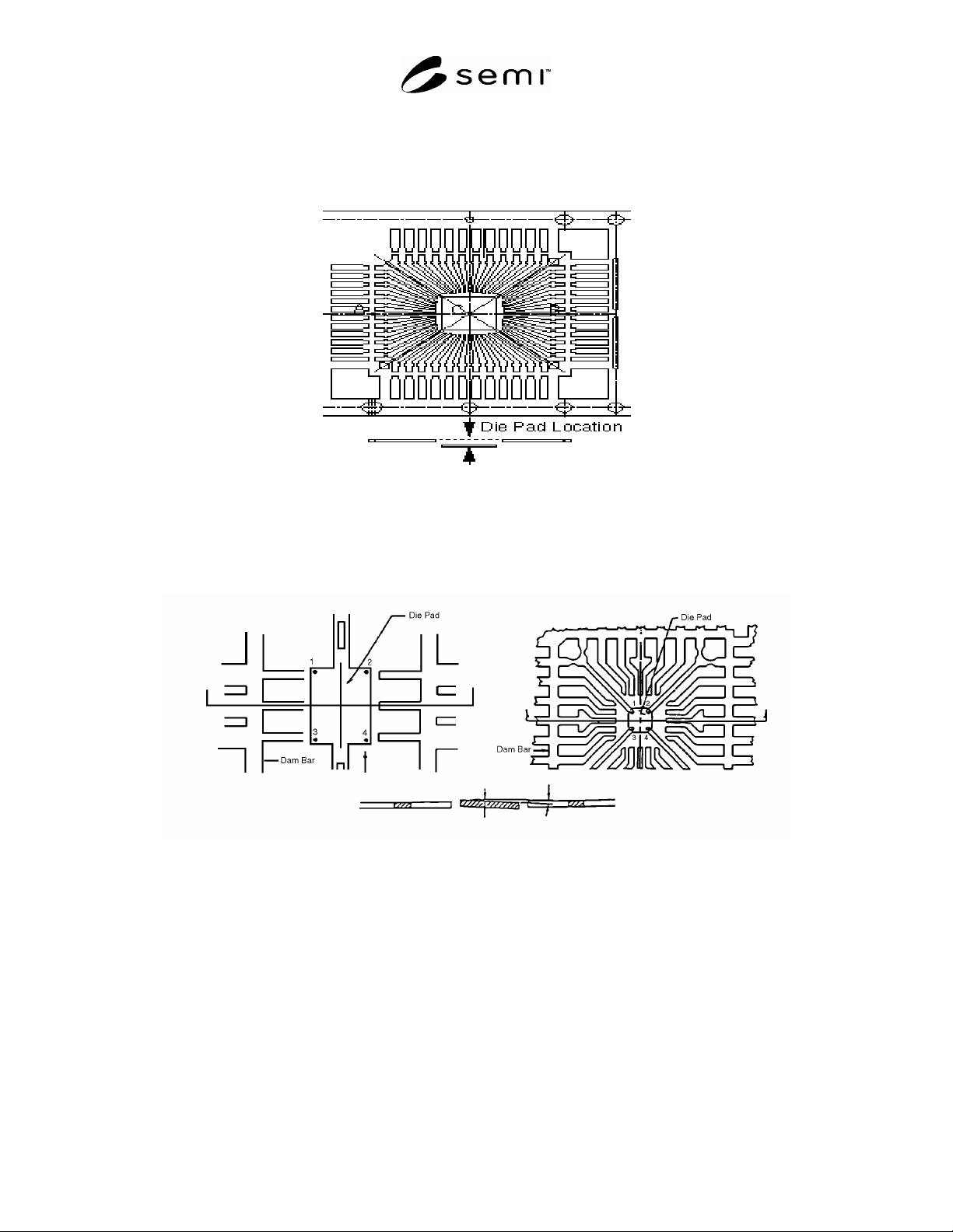
4.1.8 die pad location — deviation of the center point of die pad surface from a plane established by the dam bars
(see Figure 7).
Figure 7
Die Pad Location
4.1.9 die pad tilt — deviation of the plane of die pad from a condition parallel to the plane formed by the dam bars
(see Figure 8).
Figure 8
Die Pad Tilt
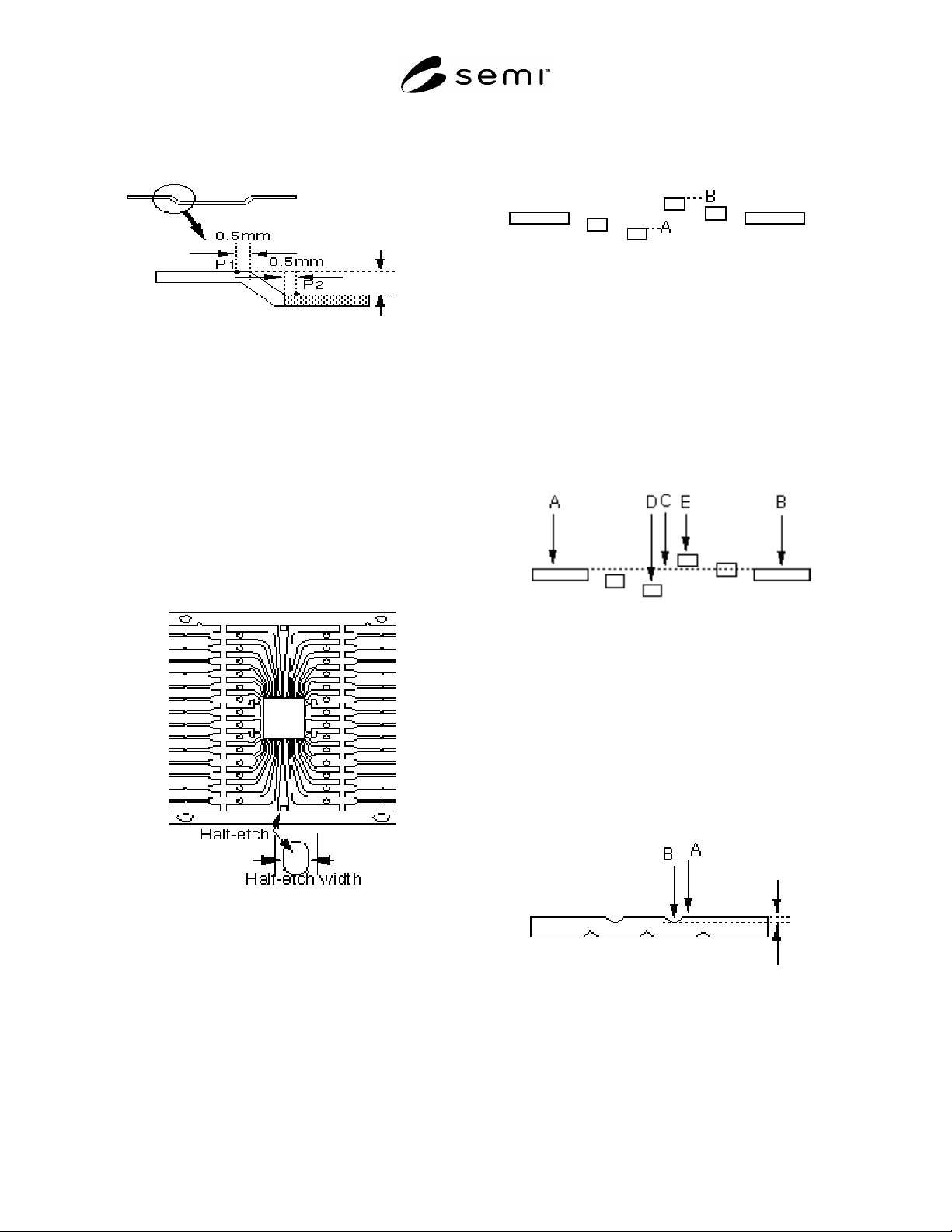
4.1.10 downset depth — (see Figure 9).
SEMI G70-0996 © SEMI 1996, 2004 4
Figure 9
Downset Depth
NOTE 3: The measurement points P1 and P2 should be
agreed between user and supplier.
4.1.11 half-etch — some designed part or area of
leadframe where the thickness is reduced by one side
etching.
4.1.12 half-etch depth — the maximum depth of the
half-etch (see Figure 10).
Figure 10
Half-Etch Depth
4.1.13 lead coplanarity — total indicator reading
difference of the lead tips in the Z direction (see Figure
11).
Figure 11
Lead Coplanarity
4.1.14 lead planarity — total indicator reading of the
lead tips in the Z direction relative to the datum formed
by the dam bars (see Figure 12).
Figure 12
Lead Planarity
4.1.15 lead lock groove — a groove formed in leads
using the half-etching technique or stamping to increase
the adhesive strength of plastic molding compound to
the leads and improve resistance to water intrusion into
the package (see Figure 13).
Figure 13
Lead Lock Groove
4.1.16 lead lock groove depth — the maximum depth
of the groove.