semi合集-English.pdf - 第2968页
SEMI E120-0705 © SEMI 2003, 2005 4 7 Background 7.1 This specification docum ents common characteristics of equipment in a single specification tha t can be referenced and used by other standards. These ot her standar ds…
SEMI E120-0705 © SEMI 2003, 2005 3
6.2.6 Constraints
6.2.6.1 Constraints in UML are shown with dotted lines, typically with a note attached to explain the constraint.
Constraints shown in this way tend to clutter large UML diagrams. Therefore, in this specification, constraints are
shown only on the diagrams focusing on individual classes.
6.2.7 Association Navigability
6.2.7.1 UML associations include the concept of “Navigability”. When an association is navigable, the association
may be traversed to reach the class instance at the opposite end of the association (target object).
6.2.7.2 By default, an association is navigable in both directions. If an arrowhead is shown on one end of an
association, then navigability exists only in that direction.
6.2.7.3 From any object, it must be possible to obtain a reference to the target objects of any of its navigable
associations.
6.2.7.4 The method of referencing the target objects is implementation dependent and is not specified in this
document.
6.2.7.5 Any implementer or subordinate standards mapping the concepts of this specification to an implementation
method shall specify the means of referencing the target object of an association from the source object.
6.3 Model Extension
6.3.1 Any concrete class in the CEM model can be extended. Extension is achieved through association. In
“extension by association” the new capability is contained in a separate class that is related to the original by an
association. In the case of CEM, an “Extension” class has been added to the model (see ¶8.5.3.4) along with the
needed association.
6.3.2 The Extension class is associated with Nameable, so that any Nameable can have multiple Extensions. The
Extension class has no attributes or services and does not itself add anything to the extended CEM class. To have a
meaningful extension, a subclass of Extension must be created containing the new features.
6.3.3 So, in order to create an extension to a selected concrete CEM class, a new class would be designed with
added features. For instance, it might contain a new attribute. This new class would be designed as a subclass of
Extension. Remember that any Nameable can navigate the association to any of its Extensions. Therefore, the new
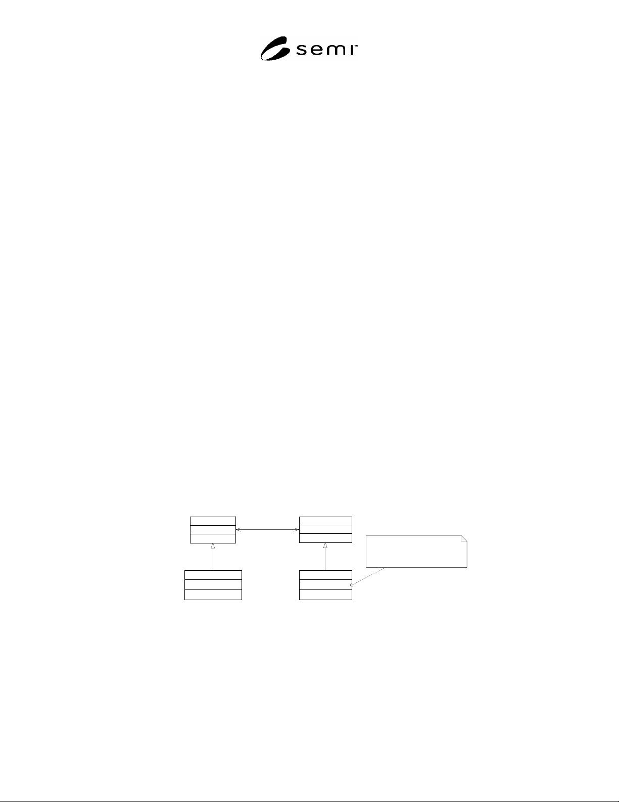
subclass of Extension could be associated with any CEM class. See Figure 1 below for an illustration. The final
step is to associate the new Extension subclass to the specific CEM class it is extending.
6.3.4 Most extensions will be designed to work on specific CEM classes. The CEM model does not enforce
matching an extension with its intended CEM class. Therefore, the specification of the Extension class must
describe its allowed usage.
Nameable
Extension
extensions
0..*
CEMClass
NewAttribute:string
CEMClassExtension
CEMClass inherits the association with
Extensions - it may have an associated
CEMClassExtension and thus gain
access to the NewAttribute
1
target
Figure 1
CEM Model Extension
6.3.5 The scope of CEM is limited to static information about the equipment. However, that limitation does not
apply to extensions. So extensions might include static or dynamic attributes as well as links to state models or
other complex constructs. An example of an extension that might be added by a supplier is a class containing
“manufacturedDate” and “serviceTagNumber” attributes to be applied to an Equipment object.
SEMI E120-0705 © SEMI 2003, 2005 4
7 Background
7.1 This specification documents common characteristics of equipment in a single specification that can be
referenced and used by other standards. These other standards are expected to extend the Common Equipment
Model to add characteristics unique to that standard. Thus, this specification attempts to be the core of a single,
coordinated object model of the equipment with the full model being a composite of multiple standards.
7.2 Approach to Model Description
7.2.1 Class Model vs. Instance Model
7.2.1.1 A model showing the specifics about particular equipment is considered an “instance model”. Each
equipment instance model will have its own characteristics based on its function. No single model can directly
describe all such instances. Instead, the class model contained in this specification defines the classes to be used to
describe the equipment’s structure and how they shall relate to one another. The instance model of the equipment is
to be provided by the equipment supplier as specified by the CEM class model.
7.2.2 Model Extensibility
7.2.2.1 The Common Equipment Model is intended to be extensible (within defined limits). ¶6.3 describes
acceptable ways to extend the model.
7.2.2.2 The instance model of the equipment shall thus be constructed by the equipment supplier based on
the classes defined in this document,
extensions to this model defined in other SEMI standards, and
extensions to the standardized model made by the supplier to address unique equipment characteristics.
7.2.3 External View — Not Equipment Design
7.2.3.1 There is no expectation that equipment suppliers will use the model specified in this document as the basis
for the design of their equipment. The CEM is intended to provide a structure to promote clear communication. It
needs to provide an unambiguous view to the factory host that is representative of the equipment and meets the
needs of the host.
7.2.4 Communication Not Defined
7.2.4.1 This specification leaves to other SEMI standards the definition of how the Common Equipment Model will
be communicated (in whole or in part) between the equipment and the factory host. It is to be expected that there
will be many uses for the model and the details of communication are best defined in context with planned use.
7.2.5 Behavior Not Defined
7.2.5.1 In order to keep the model simple, this document does not define behavior of classes in the CEM. Class
behavior is related to function, and thus to functionality supplied by the equipment interface. This functionality and
behavior is left to other SEMI standards to define.
7.2.6 Applicability
7.2.6.1 Though the CEM attempts to address all semiconductor related factory equipment, it is recognized that this
may not be possible. The CEM covers only manufacturing equipment (i.e. equipment that perform their function on
material—e.g. no independent environmental monitoring systems, etc.). The vast majority of semiconductor factory
equipment should be able to comply with this specification.
7.3 Uses For The CEM
7.3.1 In order to understand the CEM, it is necessary to understand expected uses of the model. While it is not
possible to anticipate every possible use, the following list presents several expected uses that may be defined by
other standards.
7.3.2
Equipment Self-Description Using Metadata — An important consideration for the integration of
semiconductor equipment into the factory is the ease with which the equipment’s structure and capabilities can be
understood and translated into functioning software. With traditional semiconductor communication technologies
this is achieved by first reading the equipment supplier’s communication manual and then configuring or coding
SEMI E120-0705 © SEMI 2003, 2005 5
factory software to match the documentation. Unfortunately, manuals are too often incomplete or out of date. If the
equipment can provide its instance model (and the extended class model on which it is based) to the host, it is more
likely to be complete and accurate. If it can construct that model in real-time, based on its current hardware
configuration it will be more accurate. This self-descriptive data is also known as “metadata”.
7.3.3 Relation Of Data To The Equipment — Data gathered from equipment gains greater meaning if it is clear as to
what part of the equipment it pertains and what related data items provide context information. The instance model
can be a reference in the definition of the data collection plans and reflected by actual data collected.
7.3.4 Relation Of Parameters & Setting To The Equipment — Proper and predictable control of equipment is
possible only if the effects of all available parameters and settings is understood. These must be related to the
equipment and to the measurable values that they affect. This information can be provided by the instance model.
7.3.5 Understanding Equipment Capabilities — The process capabilities of equipment depend on the modules
present and the characteristics and status of those modules. In some situations, the hardware configuration of
equipment can change on a regular basis.
8 Common Equipment Model Definition
8.1 This section documents the Common Equipment Model.
8.2 Overview
8.2.1 Documentation of the Common Equipment Model begins with system views of the model and moves to
detailed descriptions of the classes with their attributes and relationships. No behavior is defined—that is, no state
models and no methods are described for classes.
8.2.2 It is important to note that the two system views presented are of the same model. They are separated to avoid
large, complex diagrams, thus enhancing understandability.
8.2.3 The model shows only classes and their relationships. Actual equipment will have corresponding instance
models that define the detail of the equipment as viewed through an equipment interface. Thus, the Common
Equipment Model in this document provides rules for constructing the instance model of an equipment.
8.2.4 The Common Equipment Model is represented in two system level views. The first is the inheritance
hierarchy that shows which classes inherit characteristics (e.g. attributes and relationships) from which other classes.
The second view represents the relationships among classes to show general equipment structure. These views are
described in general terms to highlight important aspects of the model.
8.2.5 Everything in these two views is repeated in subsequent sections dealing with individual classes in the model.
In the individual class views, class of interest is shown with all relationships to other classes. No other detail is
shown in these views.
8.3 Inheritance Hierarchy
8.3.1 The inheritance hierarchy view, Figure 2, shows the superclass/subclass relationships of the Common
Equipment Model.