semi合集-English.pdf - 第4867页
SEMI M1-0305 © SEMI 1978, 2005 43 RELATED INFORMATION 1 SURFACE METAL CONTAMINATION NOTICE : This related information is not an official p art of SEMI M1 and is not intended to modify or supersede the official standard. …
SEMI M1-0305 © SEMI 1978, 2005 42
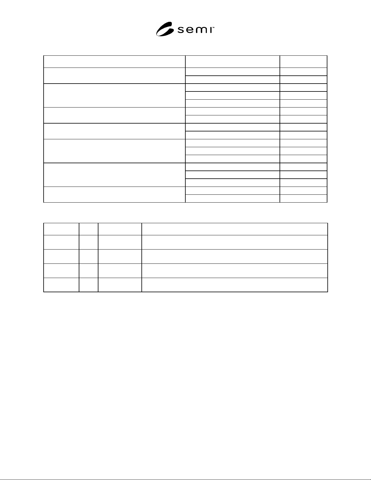
Table A2-1 Variables in Shape Quantities
Variable Options Code
Global G Measurement Method
Local (Site) S
Front F
Median M
Reference Surface
Back B
Least-Square L Reference Plane
3-Point 3
Yes Y Corrected for Gravitational Sag
No N
Front F
Median M
Measurement Surface
Back B
Full Scan (Entire) E
Partial Scan P
Measurement Pattern
Centerpoint C
Range (TIR) R Parameter
Maximum RPD D
Table A2-2 Shape Code Summary
Code Term Test Method Expanded Form of Code
GFLYFER sori SEMI MF1451 Global, Front-surface Least-squares reference plane, Yes (corrected for gravitational
sag), Front-surface measurement, Entire surface scanned, Range
GMLYMER warp SEMI MF1390 Global, Median-surface Least-squares reference plane, Yes (corrected for
gravitational sag), Median-surface measurement, Entire surface scanned, Range
GM3YMCD bow SEMI MF534 Global, Median-surface 3-point plane, Yes (corrected for gravitational sag),
Median-surface measurement at Center point, Deviation
GB3NMPR warp SEMI MF657 Global, Back-surface 3-point reference plane, No (not corrected for gravitational
sag), Median-surface measurement, Partial surface scanned, Range
SEMI M1-0305 © SEMI 1978, 2005 43
RELATED INFORMATION 1
SURFACE METAL CONTAMINATION
NOTICE: This related information is not an official part of SEMI M1 and is not intended to modify or supersede
the official standard. Approval was by full letter ballot procedures with publication authorized by the NA Regional
Standards Committee beginning with the 1995 edition of the standard. Determination of the suitability of the
material is solely the responsibility of the user.
R1-1 Scope
R1-1.1 Maximum allowable surface metal contamination levels for wafers to be used in integrated circuit (IC)
fabrication generally depend upon the IC device density and upon the IC process design. In general, as the device
density increases, the allowable surface metal contamination levels become lower.
R1-1.2 This related information is intended to provide guidance regarding allowable surface concentrations of metal
contaminants that have been reported to be deleterious to circuit and device performance.
R1-2 Suggested Allowable Surface Metal
Contamination Levels for 1 µm Geometries
R1-2.1 Table R1-1 lists suggested surface metal limits for
circuits and devices with a minimum linewidth in the
range of 0.8 µm to 1.2 µm for two alkali metals (Na, K), a
light metal (Al), and five heavy metals (Cr, Fe, Ni, Cu,
Zn). These are same elements as are listed in the items
under Section 2-7 of Table 1, Part 2, and they are listed in
the same order as they appear in that table.
Contaminant levels in Table R1-1 are significantly higher than
would be allowed for leading edge technologies at the time of
approval of this standard.
R1-3 Test Methods
R1-3.1 The test methods suitable for use in determining
the levels of each surface metal contaminant are listed in
the items under Section 2-7 of Table 1, Part 2. This list
and the related discussion of these test methods in Related Information 2 should be referenced in selecting methods
appropriate for testing the individual surface metals.
Table R1-1 Suggested Polished Wafer Surface
Metal Contamination Limits Appropriate to Circuits
and Devices with a Minimum Linewidth in the
Range 0.8 µm to 1.2 µm
Element Contaminant Level
Sodium (Na)
Not greater than 1 10
11
atoms/cm
2
Aluminum (Al)
Not greater than 1 10
11
atoms/cm
2
Potassium (K)
Not greater than 1 10
11
atoms/cm
2
Chromium (Cr)
Not greater than 1 10
11
atoms/cm
2
Iron (Fe)
Not greater than 1 10
11
atoms/cm
2
Nickel (Ni)
Not greater than 1 10
11
atoms/cm
2
Copper (Cu)
Not greater than 1 10
11
atoms/cm
2
Zinc (Zn)
Not greater than 1 10
12
atoms/cm
2

SEMI M1-0305 © SEMI 1978, 2005 44
RELATED INFORMATION 2
TEST METHODS
NOTICE: This related information is not an official part of SEMI M1 and is not intended to modify or supersede
the official standard. This information was developed during the revision of this standard in 2004. It is based in part
on information previously published as part of SEMI M28, withdrawn in October 2000. Approval was by full letter
ballot procedures with publication authorized by the NA Regional Standards Committee on November 4, 2004.
Determination of the suitability of the material is solely the responsibility of the user.
R2-1 Scope
R2-1.1 This Related Information Section discusses aspects of the various test methods listed in Table 1 together
with additional information about other test methods that are not listed in Table 1 but either have been or still are
used in the industry.
R2-1.2 The next section contains references to the test methods that are not cited in the main body of SEMI M1 but
that are discussed here. The various test methods are discussed in order that the items they cover are listed in Table
1.
R2-1.3 Note that silicon wafers are extremely fragile. While the mechanical dimensions of a wafer can be
measured by use of tools such as micrometer calipers and other conventional techniques, the wafer may be damaged
physically in ways that are not immediately evident. Special care must, therefore, be used in the selection and
execution of measurement methods.
NOTICE: This section does not purport to address safety issues, if any, associated with its use. It is the
responsibility of the user of this standard to establish appropriate safety and health practices and determine the
applicability of regulatory or other limitations prior to use.
R2-2 Referenced Standards
R2-2.1 The standards listed in this section are referenced only in this related information. See Section 4 for other
standards that are referenced in this related information.
R2-2.2 SEMI Standards
SEMI M49 — Guide for Specifying Geometry Measurement Equipment for Silicon Wafers for the 130 nm
Technology Generation
SEMI M50 — Test Method for Determining Capture Rate and False Count Rate for Surface Scanning Inspection
Systems by the Overlay Method
SEMI M52 — Guide for Specifying Scanning Surface Inspection Systems for Silicon Wafers for the 130 nm
Technology Generation
SEMI MF43 — Test Methods for Resistivity of Semiconductor Materials
SEMI MF154 — Guide for Identification of Structures and Contaminants Seen on Specular Silicon Surfaces
SEMI MF398 — Test Method for Majority Carrier Concentration in Semiconductors by Measurement of
Wavenumber or Wavelength of the Plasma Resonance Minimum
SEMI MF723 — Practice for Conversion Between Resistivity and Dopant Density for Boron-Doped, Phosphorus-
Doped, and Arsenic-Doped Silicon.
SEMI MF1527 — Guide for Application of Silicon Certified Reference Materials and Reference Wafers for
Calibration and Control of Instruments for Measuring Resistivity of Silicon
SEMI MF1529 — Test Method for Sheet Resistance Uniformity Evaluation by In-Line Four-Point Probe with the
Dual-Configuration Procedure
SEMI MF1618 — Practice for Determination of Uniformity of Thin Films on Silicon Wafers
SEMI MF1810 — Test Method for Counting Preferentailly Etched or Decorated Structural Defects on Silicon
Wafers